


If new LEDs or marine electronics are your horizon, you’ll soon find yourself tangling with tiny wire connections that seem so fragile it’s hard to imagine any crimp or connector providing the reliability we need in marine systems. Although it’s fairly easy to create a reliable crimp or connection between size AWG 12 wires (about 2mm in diameter) used to power many 12-volt accessories, once the wire sizes start creeping down toward AWG 22 (about .6mm in diameter) commonly used in data cables and low power LEDs, creating robust connections requires some specialized tools and techniques.
Over the past few years, marine expert Rod Collins of Marine How To and Practical Sailor Technical Editor Drew Frye have evaluated various small wires connectors on the market for Practical Sailor. Their reports have given sailors a list of tools and techniques that make it easier to join tiny wires, and to ensure that they stay joined. The links to those reports are at the bottom of this page, and you should read those to get a complete picture of this topic.
First a bit of background.
ABYC Standards
The American Boat & Yacht Council (ABYC) is fairly explicit about what connections are permissible under its voluntary guidelines, but there is a lot of wiggle room:
Wiring connections shall be designed and installed to make mechanical and electrical joints without damage to the conductors. Solder-only connections are not allowed. The connector cannot breaks or damage fine strands.
Metals used for the terminal studs, nuts, and washers shall be corrosion resistant and galvanically compatible with the conductor and terminal lug. Aluminum and un-plated steel shall not be used for studs, nuts, and washers.
Terminal connectors shall be the ring or captive spade types.
EXCEPTION: Friction-type connectors may be used on components if:
1) The circuit is rated not more than 20 amperes or the manufacturers rating for a terminal designed to meet the requirements of UL 310, Electrical Quick-Connect Terminals; or UL 1059, Terminal Blocks, and 2) The voltage drop from terminal to terminal does not exceed 50 millivolts for a 20-amp current flow, and 3) The connection does not separate if subjected for one minute to a six-pound (27 Newton) tensile force along the axial direction of the connector, on the first withdrawal. For comparison, the standard generally applied for home electrical systems (UL 486C) is 10-25 pounds for wire nuts and spring clamp splices, depending on wire size, and 30-70 pounds for screw-clamped terminal strips.
Connections may be made using a set-screw pressure-type conductor connector, provided a means is used to prevent the set-screw from bearing directly on the conductor strands. Some choc block and DIN rail connectors have these, and some do not. UL 486A and C, referenced by the Coast Guard, also emphasize the need for protecting wire strands from direct screw contact.
Types of Fittings
Based on our testing, barrier blocks (aka terminal strips) with screws for joining ring-eye terminals are the preferred option for joining multiple wires whenever practical. The connections are easy to inspect, clean, and protect with a thin coating of corrosion-inhibiting grease. But this option isn’t always the most practical, especially with smaller wires. We’ve explored pros and cons of various splices and soldered connections sealed with heat shrink seals in previous reports.
What follows is a brief summary of our extensive research on marine wiring and connectors and focuses primarily on multi-wire terminal fittings suitable for tiny wires and can be used with or without DIN rails. The links listed below provide more details, and for the most complete information on this and related topics, with detailed photos, download the PDF issue where the report was first published. (The PDF issue is in the Practical Sailor Full Issue Archive and is the issue AFTER the initial month of publication which appears at the top of each online report.)
DIN rails. These rails provide a modular platform for terminal blocks. Newer boats use these rails to mount wires, connectors, and switches. They provide a compact, orderly way to organize wiring. Use aluminum rails; thinly galvanized rails sometimes corrode, making service difficult.
Spring-loaded connections. Common in household 120-volt wiring, the wire is simply stripped and forced into a hole. These are only rated for solid wire. They may be compliant if you crimp pins onto the wire ends, but we avoid them. This problem is most often encountered when installing 120-volt outlets using what amount to household outlets; use only receptacles that accept ring terminals.
Screw terminal blocks. This group includes so-called choc blocks, short for chocolate blocks, because they can be snapped to length. If there are at least six screws, they can be screwed to a panel with two screws. A set screw bears directly on the wire strands. They are only suitable for solid wire, which are explicitly banned by ABYC. Coarser strands (16 AWG larger) THHN wire will hold up reasonably well, but fine instrument wires are normally ruined.
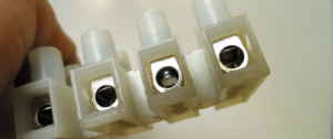
A preferable subset of the screw-terminal block style includes a compression plate. The set screw pushes on the plate, and the plate secures the wire. There may be a few subtle grooves to increase friction, but nothing that can damage the strands. For wires smaller than 20 gauge, consider neatly doubling the end if you can’t get a good bite. These are ABYC compliant, so long as the components are tin plated and meet the corrosion resistance and galvanic compatibility requirements, which they ordinarily do. It may be acceptable to insert more than one wire to add branches, but only in smaller gauges.
Barrier blocks. The standard for most marine applications using typical wire sizes, these are very secure if the wires terminate with crimped-on rings or retained fork fittings. Better quality blocks are constructed of tin-plated copper and stainless steel, and are very corrosion resistant. With the addition of jumpers, you can add branch circuits. Using these with smaller wires can be problematic, since it requires crimping on terminal fittings.
Wago lever-style connectors. These are most often used free floating as a wire nut replacement, but they can be DIN rail mounted with addition of a matching mounting bracket and can be panel-mounted using a matching strain relief bracket. They operate much like a rope clutch; raising a lever lifts a spring loaded clamp, allowing even thinly stranded wires to be easily inserted. Lowering the lever locks the wire firmly in place. Like a jammer, if the lever is raised again, the wire can be removed, and they can be used over and over again.
Soldering the ends stiff is often suggested as a way of increasing durability with many of these connector types, perhaps even making the push-in, spring loaded type safe. This is not true. Under high mechanical load the solder will deform, loosening the connection and allowing strands to cut. If the connection is overheated (and this does not need to be to the solder melting point) only enough to soften it ever so slightly-the wire will deform and the joint will come loose. Cycled a few times, they can literally fall apart. Tinned wire is OK, but do not prep the wire ends in any way other than twisting. Crimping a pin onto the wire end should be a last resort, and weve never seen the need for it on a boat.
Because there is no crimp or heat shrink to provide strain relief, be careful to support wires within a few inches. We’ve seen a lot of small instrument wires snap off due to vibration.
Posi-lock. Superficially resembling Sta-loc rigging terminals, we had high hopes. To install on SAE wire, strip the wire back as directed. For tinned marine and THHN machine wire, strip about 1/16 inch less than described by the instructions, or a bit of uninsulated wire may be exposed. Insert the wire until it extends about 1/16 inch past the opening. Thread the ferrule onto the center portion and snug tightly.
There are other types, but they are not suitable for stranded wire. For more details on the various connectors, crimps and splices that work, and those that don’t check out the following three reports from Collins and Frye.
Out Out, Brief Wiring Terminals
How to Connect Small Wires
Small Wire Connections Part II
Heat Seal Connectors
If you’ve got a major rewiring project that involves adding more than just a data repeater or LED lights, our recently expanded six-volume eBook “Marine Electrical Systems,” explores everything from properly grounding 120V – AC systems, to “fishing” wires through tight conduits, to choosing the most reliable connectors and cables for your mast-mounted antennae (it’s not the cable most OEM boat manufacturers use). You’ll also learn which connectors and anti-corrosion measures will create bulletproof connectors for places that commonly get wet.


Proofreading could be your friend. Embrace a New Friend!!
I agree.
While I enjoyed the article, some additional detail/clarity could prevent readers from down the wrong path. ABYC E-11 is very specific about wire size. Your article would give the reader the idea that 22 AWG wire is fine to use for LED wiring. In fact ABYC stipulates that 16 AWG is the smallest gauge that can normally be used in a marine application. This is the baseline. ABYC calls out a few exceptions where 18 AWG is permitted. Anything smaller is ONLY allowed for a very limited number of items that are VERY low power and that are properly sheathed/bundled.
Hmmm… Not sure I am with you on this. In my primary field (theater) I have similar challenges and I have always believed that the connection should never take any mechanical load. Solder is a guarantee that the joint will be always be solid and will endure any non-catastrophic vibrations. Stress relief is accomplished by other means outside the actual conductor joint.
After six years of working in the coastal and marine environments in and round AF and ME for the USG, A couple of things to mind when using solder, much if not most solder used in electrical work is equipped with resin, which under much electrical system is not an issue but under salt water vapor becomes a a big issue as resin absorbs moisture. I use IPA and “Q”-tips to remove as much of the resin as possible. The other thing that comes to mind is that some of the newer solders (reduced lead) appear to corrode faster in these salt “air” than the old standby 60/40. I have no hard data on this second issue only some empirical data drawn from experiences
Not so sure that I can agree with your advice or conclusions.
Although ABYC correctly states that minimum sizes for wire to be used and provides the exception for low power data cables that are bundled or sheathed, the article then goes on to push for barrier block connectors and crimped connections, which are both hard to crimp and very unreliable on 20 gauge and up – stranded wires.
Barrier blocks and the crimps to ring connectors, introduce many more failure modes and leave the very small wires exposed to vibration, corrosion, as well as potential mechanical damage
The best solution I have seen and used for over 30 years without any failures is to tin each connection, slide a piece of suitable sized double wall + glue filled heat shrink on the wire, then solder directly to the next wire, test connection, wipe off all remaining rosin from the soldering operation, then shrink the heat shrink sleeve over the connection. This will support and provide full strain relief, prevents vibration at the solder joint to strand interface and fully water proofs the connection for life.
This approach is routinely used on deep diving systems and manned submersibles with excellent results.
Please note that only solder specifically suited to electronic wire and board connections shall be used.
The errors in this article make it hard to understand and trust. It would also be helpful to have images with the different types of connectors. I will be wiring my boat within the next year and I am more confused now than before I read this.
I have no comment on the things I believed were errors since I lack sufficient specific expertise to be sure I am correct. BUT, I believe the lack of illustration (preferably photographs) of each type of fitting and other mentioned components would have been very helpful for “don’t know quite enough” persons such as me.
It would be good for an article like this to have more pictures. Not all of us cruisers know advance electricity to know what “Wago lever-style connectors” are. Yes, each one of us can search, but you could do it once for all of us.
If many of the commenter’s would have taken the time to click on the included links to the other articles they would have found illustrations of the listed equipment and much more information as well as test results. These summaries have always been a means to try and sell their more complete series but I do agree, that including those photos would have helped this sample. Take the time to click the included links. I have found this series very helpful as even on my new boat I have found some, let’s say “interesting”, wiring decisions.
I’ve added photos to clarify this blog post. Like all my blog posts, its purpose is to share information with sailors, not to sell anything. PS marketing department (more than a thousand miles away from me) does send out magazine excerpts to encourage subscriptions and book sales that support our ad-free testing, so it is easy to confuse the two. But even their mission is the same as mine, to continue a nearly 50-year-old tradition of objectively reporting on sailboats, gear, and seamanship without any advertising. They do, of course, like to watch the bottom line. I honestly don’t.
Subscribers can control emails they get here. https://www.practical-sailor.com/customer-service
A previous blog post detailed ways to get the most out of your subscription.
https://www.practical-sailor.com/blog/get-the-most-out-of-practical-sailors-subscriber-services
Not able to agree with a lot of this article. When using wire above 20 AWG a crimped connection or barrier block is the least recommended option of securing small wires. As stated by other tinning or soldering the connection and heat shrinking (appropriate sized shrink tube is a much as well) is the platinum standard. I don’t like to gripe but I think that this could misinform people who might not know any better. Maybe state some of the concerns from the comments section as a disclaimer?
What! No mention of ferrules? To me they’re essential in small wire connectors on auto pilots etc. Also good on euro connectors.
Soldering is expressly forbidden by ABYC as the sole mechanical means of securing wires. Solder plus nearby strain relief is not acceptable. It must be a crimp or clamped connection. I too have soldered many wires without failure, but the rule has changed. The risk, of course, is that in the event of overload the solder can soften and a loose, hot wire can result.
In fact, solder joints have been proven to be less tolerant of vibration than other connection types. They fail from fatigue at the solder boundary. I have reproduced this testing, and it was… vivid. You can believe it or not, but ABYC does. I’ve had wires snap off instruments due to fatigue at the solder boundary, right through the heat shrink. Too much of a stress riser.
I should have called out ferrules (I did mention crimping on a pin), but I did mention that only pressure plate style blocks are acceptable for stranded wire. If proper blocks are used, ferrules are not required.