


Following our review of the new J/133 (PS Oct. 1, ’04), in which we recounted a chainplate failure aboard hull No. 3 on its maiden voyage, a reader’s letter prompted us to review the manner in which manufacturers design and construct the critical connections between mast, shrouds, and a boat’s structure. In the case of the J/133, we concluded that the construction method—a contemporary yet time-tested approach—was properly conceived, but poorly executed.
The folks at J/Boats declined to offer specific comments, but the boat’s builder—Pearson Composites, LLC (formerly TPI)—told us that ours was a fair assessment of the situation. (More on that later.)
Nonetheless, the issue of chainplate construction and rig attachment demands further examination, particularly for the owners of older boats whose vessels may be susceptible to chainplate failure.
Like the human anatomy, which is supported by a series of bones connected at joints (“head bone connected to the neck bone, neck bone connected to the shoulder bone”), a sailboat’s standing rigging reflects many similar connections. At one end of any stayed rig, the head of the mast is supported by stays and shrouds that in most cases disappear belowdecks to connect to a metal, wood, or fiberglass section that itself is attached to a bulkhead, the hull’s topsides or bottom, or an interior grid system.
With any rig, contrary forces are at work. At the masthead, tensioned shrouds pulling chainplates upward from a grid in the bottom of the hull, for instance, are at the same time pushing the butt of the mast, or a compression post, in the opposite direction. Consider that the headstay and backstay are pulling the bow and stern upward, and the conflicting forces on the entire structure are enormous.
“The static pressure on the hull of the Santa Cruz 70 produced by the mast, with the boat sitting static at a dock, is approximately 28,000 pounds,” explained Lance Brown, president of Santa Cruz Yachts. Given that, it’s no surprise that America’s Cup boats, which take advantage of every weight-saving method available, often have major failures.
Creating a proper set of connectors, then, requires that designer, engineer, boatbuilder, and rigging specialist each scientifically calculate the loads that will act on the sails in wind and sea, and the loadbearing capacity of the standing rigging, which will ultimately determine the lamination schedule for chainplates or the appropriate strength characteristics of whatever material is used to fabricate these critical connectors.
Ty Goss, of the custom sales division at Navtec, told us that “Once the loads on rigging and turnbuckles are determined, our prototypes are tested by running fatigue tests.
“We will load a turnbuckle to its breaking strength and stress it 120,000 to 200,000 times (1.4 times its projected life expectancy) in 15-second cycles. If it doesn’t break, we know we have the right product.”
On older boats, chainplates were often fashioned from necessary, but unsightly, metal straps attached to the exterior. Unless an owner diligently polished them, the straps or their fittings typically rusted, which produced blemishes on the topsides. These same rust lines, however, could provide an owner with visible evidence of the potential deterioration of the plates, or their fasteners.
On modern fiberglass boats, chainplates are usually out of sight and out of mind. As builders became more confident of the bonding capacity and strength of fiberglass, they began relocating these straps on the hull’s inner skin, or bedded in bulkheads. However, as with the exterior attachments, the new method was not without its drawbacks, since a leak at deck level could result in delamination of the fiberglass, or a waterfilled core; either condition reducing the structural integrity of the components.
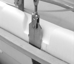
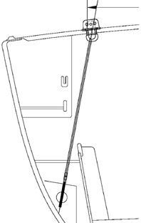
Various methods of attaching plates are used, including the method employed by Pearson Composites, LLC in the construction of the new J/133. In that case, the shrouds are connected to a deck plate, which in turn is connected to a tie rod, which is connected to a horizontal pin beddedin a fiberglass buttress in the hull. At PC, LLC, the buttress is a solid fiberglass block with a hole bored that is within 5/1000th” of the size of the pin. This basic design is not new technology; grand-prix racing boats have been employing similar designs for 20 years.
The failure of the chainplate on the J/133 was the byproduct of a miscommunication within the builder’s facility, according to Stephen A Misencik, director of engineering and design at PC, LLC.
“Miscommunications between engineering and the production floor caused the installation of the deck chainplate assembly to be located 2″ aft of where it was originally designed to be,” Miscencik told us. “This resulted in the tie rod being mis-aligned with both the deck fitting as well as the hull buttress/pinion assembly.”
The result: “When the mast and spreaders were constructed by Hall Spars, the shroud-rod connection did not line up properly, placing excessive loads on the fiberglass buttress.” Under sail in 30- to 35-knot winds and a short, steep chop on Lake Michigan, he added “the flange bond on the starboard side on Hull No. 3 failed. Only one edge of the buttress disbonded from the hull.”
When J/Boat’s designers and Misencik compared notes the day after the mishap, the error was discovered, and appropriate modifications completed for future boats. Only one of the five boats that were completed at that time suffered the failure, though a factory team was dispatched to rebuild each of them.
Misencik agrees that factory workers could have been alert to a problem when they encountered difficulties installing the misaligned rod during the construction process.
Coincidentally, he also describes a problem on some early models of the J/109 that were attributed to the improper use of a bonding material. In that case, chainplates were bonded to a grid framework in the bottom of the hull with ITW Plexus adhesive.
“That’s the wrong material to use when trying to produce a rigid structure from two pieces of material,” he explained. The result was excessive flex between the chainplate and the structure. The problem was corrected by replacing the bonding agent with an epoxy mix.
Dave Gerr, director of the Westlawn Institute of Marine Technology and a noted yacht designer, told us that the first calculation to be considered in chainplate design is the boat’s righting moment.
“Then, the design objective is to take the calculated loads from the shrouds and transmit them to the chainplates, without allowing the deckplate to leak,” he said.
“It is important to work out and detail the fastening of the chainplate to the hull because the loads on chainplates are immense,” he added.
Designers typically specify standing rigging and attachments, including bolts, that are 1.3 to 1.4 times stronger than the calculated load. This fudge factor is intended to offset the fact that, regardless of the material used, it will degrade over time with aging and a lack of maintenance.
“Special considerations, though, relate to the intended use of the boat,” said Santa Cruz Yachts’ Lance Brown. That company’s slogan, “Fast is Fun,” was coined by founder Bill Lee, who built a reputation for designing and constructing rocketships. His legendary Merlin was a record setting 68 footer that introduced “downwind sleds” to the sailing vernacular, and remains the precursor of a breed of boats that have evolved to become the sailing equivalent of a Ferrari.
“We built the Santa Cruz 50 and Santa Cruz 70s as race boats, so the interiors were of little consideration, allowing us to place chainplates wherever was necessary to align with the shrouds,” said Brown. Chainplates on the 50-footer were installed using a method mirroring that of the J/133. Shrouds on cruising boats, however, may be located outboard at the rail, for instance, at the expense of tighter sheeting angles and greater pointing ability. And when located outboard, they may be buried behind cabinetry as an aesthetic consideration.
“The Santa Cruz 52 (see PS review July 1, ’95), a performance cruiser, is fitted with conventional living and sleeping quarters, so we had to take into consideration the location of seat backs and shelving. We are taking the same approach with the Santa Cruz 53C, which will be introduced in April, 2005.”
One conventional method of locating chainplates out of the way is to employ flat metal sections attached to bulkheads with fasteners.
“The fastenings,” explained Gerr, “have to be adequately strong, as must the structure they fasten to, in order to distribute the load into the hull. The key to sizing the bolts is to make sure the load from the shroud does not exceed the local crushing strength of the plywood or the laminate that is added to the ply bulkhead to take the chainplate loads.
“Elongated chainplate bolt holes in bulkheads are common trouble spots. Without an adequate load bearing area, a bulkhead will eventually crush above the bolt, resulting in the chainplate pulling upward, elongating the bolt holes, and causing the chainplate to leak.” In a worst case scenario, the chainplate may pull through the deck.”
To avoid overpopulating a bulkhead with bolts, or using larger bolts, Gerr’s alternative is the installation of an annulus. “They are made of fairly high compressive strength material,” he said, “and increase the bearing area in the ply by making the annulus two times the bolt diameter.” The bolt is then installed through the center of the annulus. On older boats that evidence the potential for this type of failure, an annulus will extend the useful life of the bulkhead with a relatively easy and straightforward fix.
Brown describes the forces on chainplates, hull, and mast butt as “contrary forces in a big circle.” To disperse the loads in the new boat from Santa Cruz Yachts, the chainplate will be solid bar stock through-bolted with 12, 1/2″ bolts to a longitudinal stringer that in turn is bonded to the hull and adjoining bulkhead in multiple layers of 0 to 45-degree and 0 to 90-degree fiberglass laid in varied orientations from deck level to the keel. The bulkhead is located on the same reinforced section of the hull as the mast butt, and bonded to the hull and deck.
“That structure is so strong that we could cut the center out of the bulkhead without compromising its integrity,” Brown reported.
His comment brings to mind a common alternative to the chainplate bulkhead arrangement, which is the construction of a knee (envision an upside-down capital “L”), usually constructed of wood or fiberglass bonded to the hull and under the deck, to which the chainplate is attached. Oriented athwartships, the shape is typically long and narrow so as to accommodate furniture. In this arrangement, the chainlate resembles an inverted “T” shape and is typically cut from a single piece of stainless steel or bronze.
Though the knee is tabbed to the hull and deck, Gerr explained, “The knee’s tabbing is secondary bonding, which is structurally rather weak and can suffer from failure due to poor-quality installation, improper resin mixture,” or other factors. For that reason, manufacturers should build in “a large margin of safety,” he said, to ensure a tight structure that will endure hull and deck flex, as well as the worst of the elements.
The contemporary method of attaching chainplates involves the replacement of metal straps with tierods that are secured in the hull structure. In this instance, shrouds and rods meet at the center of two plates located on the top and underside of the deck. To produce proper angles at the intersection of the shroud and chainplate, and prevent leaks caused by the deck flexing, builders are employing self-aligning rod caps that reduce the possibility of a failure.
At the other end, in many cases the tie rod is attached to the hull or grid in a metal plate into which it is threaded; bonding to a fiberglass structure is an option. Thus, in many new boats, these shiny rods are exposed in the main saloon, but go unnoticed, allowing designers to meet an aesthetic challenge.
The Bottom Line
Modern engineering techniques and construction methods employed by major manufacturers, as well as marketing and legal concerns, are resulting in the production of better boats than at any time in the history of fiberglass, witness the number of American boats that meet ABYC and CE standards. In this environment, the odds of a structural failure are remote and, most likely, occasioned by a failure during the production cycle, or an inferior component.
The rigging on these boats, however, is not to be neglected. As Brown explained of Roy Disney’s Santa Cruz 70 Pyewacket and her sisters, “those boats were well maintained and continually inspected. Losing a race as a result of mechanical failure was unusual.”
Regardless of the age of a boat, annual inspection of standing rigging remains a must. In addition to inspecting wire for breaks, an owner should carefully examine the chainplate system from the point where it reaches the deck to its termination. Loose deck plates may result in water invading the hull or deck. Rust on the chainplate or bolts may indicate deck leaks, loose bolts or nuts producing a water leak or, in the worst case, the total destruction of the plate itself. Inspecting bolts and plates on a bulkhead is a simple matter; and removing cushions and furniture to allow inspection of the entire plate system is time well spent.
A lesser effort might just invite major failure.


