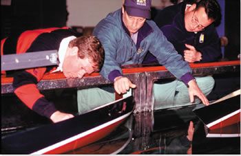
Photos by Ralph Naranjo
When the King of Sweden ordered the newly launched warship Vasa to sea in 1628, he gave little thought to the stability implications of the bronze canons perched on two upper decks. Just 1,500 yards into her maiden voyage, the Vasa capsized and sank, relegating the fire power intended to be pointed at Poland to ignominiously sink in Stockholm Harbor. This was neither the first nor last case of poorly calculated vessel stability, and todays sailors, boat designers, naval architects, and boat builders continue to debate just how much stability is enough.
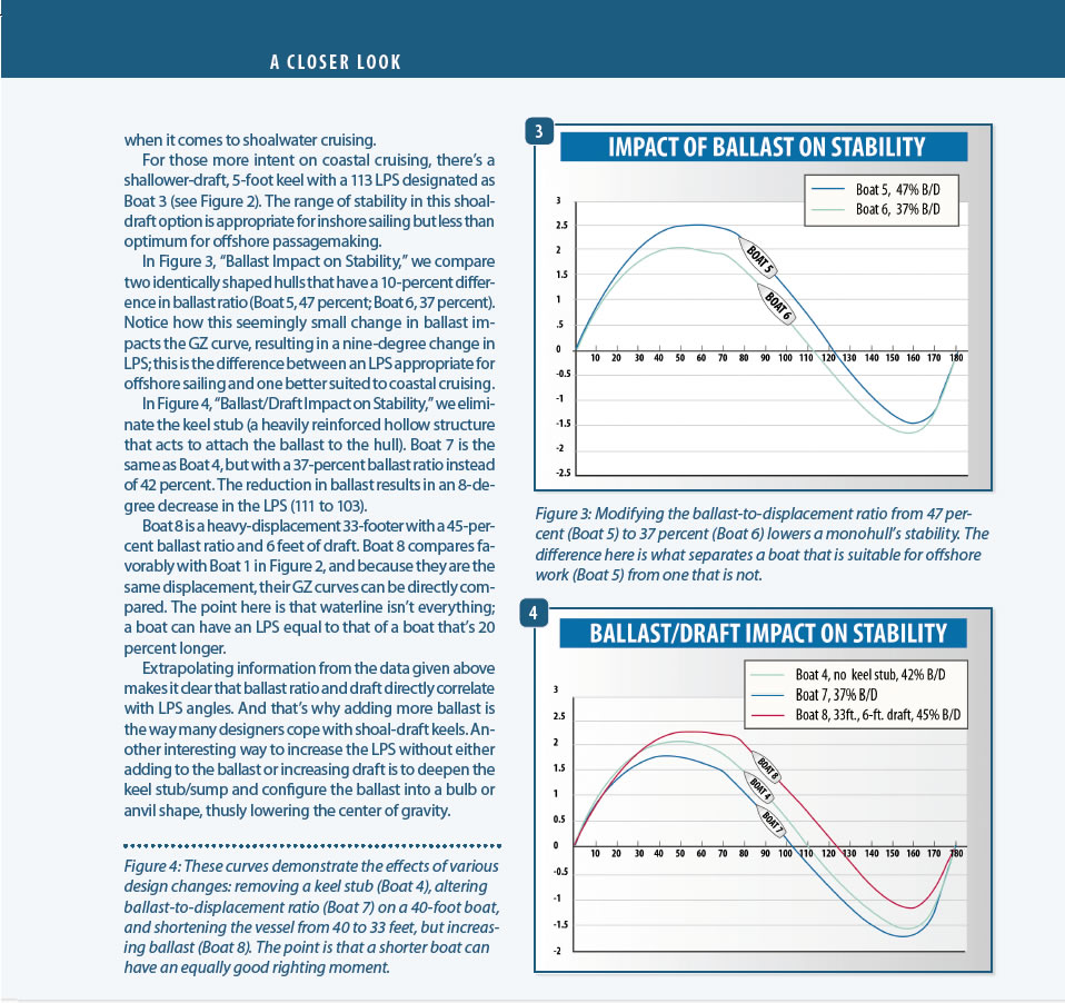
The big problem lies in how varied the voyage plans are for those of us who own the average 30- to 40-foot sailboat. A bell curve depicting usage reveals a central section thats defined by inshore and occasional coastal sailing with a pretty good chance of seeking shelter when the forecast goes bad. The even more benign segment of the curve defines sailors on Long Island Sound, the Chesapeake Bay, and other protected bodies of water that see very little effect from a fully developed sea. But a small percentage of ocean racers and cruisers at the opposite end of the bell are exposed to open-ocean encounters; they don’t have access to a harbor of refuge and must contend with whatever comes their way. Fewer and fewer 30- to 40-footers we see at boat shows meet the needs of this latter group.
Late last year, I began work on a three-part series looking at sailboat construction, stability, and performance. The first installment, Rethinking Sailboat Structure, which focused on the standards and practices used by naval architects and builders ran in the February 2015 issue. In this, the second installment, Ill look at the various factors that effect vessel stability. The final report, an examination of the many factors that impact sailboat performance, will run this fall.
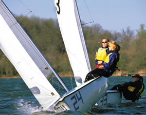
Stability 101
Around the third-century B.C., Archimedes of Syracuse came up with what was logically coined Archimedes Principle, a demonstrable phenomenon that would become one of the key elements of naval architecture. It has to do with the up-thrust force created when a hollow object is submerged. He also observed that the liquid displaced by fully submerging an object was equal in volume to the volume of the object that had been submerged. And the weight of a displaced liquid was equal to the total weight of an object afloat.
It is this buoyancy effect that becomes one of the key players in sailboat stability. In fact, the more beam thats added, the more impressive initial stability becomes. But as with all good things, there are downsides to excessive beam, stemming from undesirable attributes such as increased skin drag and the tendency to remain inverted if capsize occurs. The term initial stability is fairly self-descriptive, and relates to a sailboats resistance to tilting away out of the mast-vertical position. In such situations, the heeling moment and righting moments, which can be thought of as opposite ends of a seesaw, are zero and the mast remains perpendicular to the water plane.
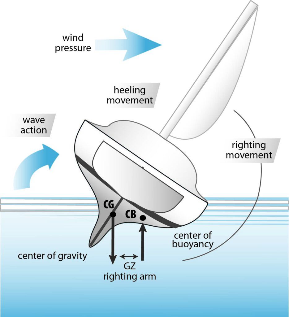
arm (GZ). The righting moment (RM) is the torque developed at specific angles of heel (the hull resists the heeling moment: RM = GZ x displacement. (Illustration by Regina Gallant)
The vertical center of gravity of any boat is a calculated midpoint around which the influence of gravity is evenly dispersed; we will refer to this point as the CG. The center of buoyance (CB) is somewhat of a sequel, but defines the center of the up-thrust force of buoyancy. The two engage in a tango of sorts, and as long as the CB remains more to leeward than the CG, the trend is toward keeping the boat upright. Once the CG moves to leeward of the CB, the boat heads toward capsize rather than resisting it, and the boat will flip over unless some intervening force takes place. The intervening force could be an abrupt change in hull shape, such as when a large watertight cabin house is immersed and moves the center of buoyancy a bit further outboard, or it could be the effect of a water plane angle change caused by a wave face that halts the capsize.
However, most naval architects would say that counting on your cabin house or a benevolent wave to keep you upright is not as reliable as well-placed ballast. Just how much ballast and where it should be placed goes to the art and science of sailboat design.
Monohull sailboat designers hedge their stay upright bet with whats become known as secondary righting moment-a force induced by ballast weight and placement that results in a lower center of gravity and adds a greater anti-capsize lever arm when its needed most, at higher angles of heel. This is not just a question of how much lead is in the bilge, its a factor that involves how far below the waterline the ballast is placed. Unfortunately, when carried to the extreme, extra-deep ballast, like an overly wide beam, can have unintended consequences. Lugging around barge-size beam increases skin drag and can create a very snap-like roll, while a 7- or 8-foot draft in a cruising boat poses some serious navigational challenges. So the real task for naval architects and yacht designers is coming up with a compromise that delivers the right amount of stability; and the first step in this decision-making process is to understand how the vessel will be used.
A key factor in this discussion is the way sail-carrying capacity is directly linked to hull shape, and thats why modern designs with wide beams carried well aft hold great appeal to performance-oriented sailors. These hull shapes shift their CB well to leeward when they first start to heel, and deliver significantly more righting moment than the lean, wineglass hull shapes of days gone by. However, as we saw in our last in-depth report on sailboat design trends, carrying a wide beam aft on a cruising boat can have a variety of unsettling effects on performance (see PS, February 2009 online).
Yes, a wide-beam boat has more skin drag and is harder to push through the water, but with the increase in righting arm, it heels less when more sail is set. All this relates to the up-thrust derived from buoyancy. Plus, the wide beam aft also provides a crew perch for hiking, which adds up to movable ballast that increases the righting moment (RM)-defined as a measure of the torque that resists heel, and expressed in the simple equation RM = righting arm x displacement.
A favored feature in the development of adequate raceboat stability is the addition of a lead bulb, anvil, or other equivalent mass at the tip or lower portion of a very deep, high-aspect ratio fin keel. The result is a multiplier effect that makes better use of a given amount of ballast, and increases righting moment at deeper angles of heel. The best way to envision this static stability tug-of-war is to think of it as a seesaw experiment in which the skinny kid lofts the local big boy by sliding his weight to very end of his lever/perch.
Cruisers arent interested in the racers perch and a rail-meat role on the windward deck, so cruising-boat designers need to add more righting moment to the equation. Water ballast and can’ting keels work, but the expense, complexity, and chance of getting caught aback with the extra ballast on the wrong side, make it less desirable for most cruisers. The trend in the cruising boat market today has led to sailboats with wider beams carried all the way aft, less ballast, and shoal draft, a threefold combo that may be acceptable for coastal/inshore cruising, but as we saw in our report on this design trend, it is less than ideal for offshore passagemaking.
Sail-carrying power and its hand-and-glove relationship to righting moment is only one aspect of sailboat stability. Another is the all-important penchant for recovery from a deep capsize, including knockdowns that reach heeling angles well over 90 degrees. Some people point out that boats with good initial stability are less likely to stick their spreaders in the water, but others point out that sailors with such boats tend to drive them harder due to their superior sail-carrying ability, and face a cliff-like dilemma when the advantage of the up-thrust of buoyancy abruptly runs out.
In order to develop a clear picture of how the righting moment changes with angle of heel, we need to start with an understanding of a GZ curve. These two letters define the righting arm, and plotting it for various heeling angles tells us a lot about sailboat stability. Imagine a graph in which the vertical axis is a yardstick depicting righting arm (GZ) and the horizontal axis is marked off in degrees of heel from 0 degrees (upright) to 180 degrees (inverted).
When viewing the curve, we need to recognize that a sailboats center of gravity (CG) is fixed; it doesn’t move as heel increases or decreases. However, the center of buoyancy (CB) moves considerably as the hull heels, submerging its volume asymmetrically. The righting moment (RM) was defined above as the vessels displacement times the righting arm (the horizontal distance between the CG the CB), and the greater this separation, the greater the righting moment (RM).
Decoding GZ Curve
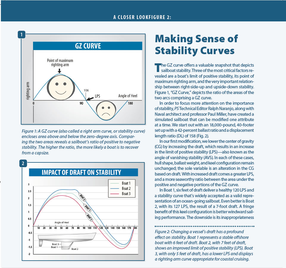
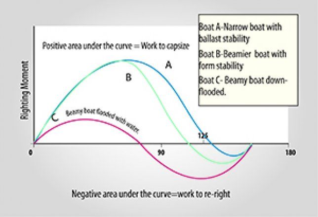
A GZ curve says a lot about the seaworthiness of a vessel, and its not just a high-peak righting arm that one is looking for. An offshore sailboat should have a limit of positive stability (also known as the angle of vanishing stability) of 120 degrees or more. An un-ballasted dinghy may capsize when heeled to less than 80 degrees, while many seaworthy offshore racers and cruisers will self-right after a deep knockdown of 120 degrees or more. Its this ability to recover from a deep capsize thats like money in the bank to every offshore passagemaker. And as Naval architect and professor Paul Miller is fond of saying-both should be a commodity with an ample reserve.
Another key indicator of a healthy design is the relationship between the area inscribed by the upright and inverted portions of the GZ curve. The area of the positive curve should be several times the area enclosed by the negative curve. The space inscribed by the positive curve is an expression of a vessels willingness to remain upright and resist capsize. The peak of the curve signifies the angle of heel where the boat is most resistant to heeling forces, and this point is defined by the largest distance between the CG and CB.
As the angle of heel increases from max GZ, the CB migrates back toward the centerline of the vessel and the righting arm decreases, eventually reaching zero. This precarious point is like a coin balanced on end and willing to flop either way with just the lightest nudge. If heeling force continues, the negative area defines a range in which a vessel will remain inverted, unless acted upon by a contravening force. Far from a favorable trait, the less area there is under the negative curve, the better. This is at least true to a point; but when designers come up with sailboats that have a Limit of Positive Stability (LPS) of 160 or more, and make the inverted stability nearly disappear, they create very deep-draft, narrow-beam, lead mines that behave more like a sea buoy than a sailboat.
Multihulls
Multihulls present just the opposite picture on a GZ curve. Their righting moment far exceeds the monohull, but it comes and goes at much smaller angles of heel. The upright and inverted areas under the curve are about equal, and the arrival of the angle of vanishing stability arrives much sooner.
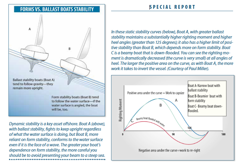
What multihull GZ and RM graphs portray are sailboats that are very resistant to heel, but these are boats that have all their righting moment banked in the initial stability basket. Thats why cruising cats tend to be smaller rigged and wide beamed, and performance cats and tris have an attentive crew ready to ease the traveler with each challenging gust. The real test in multihull sailing occurs offshore in steep seas. A slanted sea surface alters the geometry and anti-capsize contribution made by buoyancy, so effective steering on waves faces can become critical, especially in avoiding beam-on encounters with larger seas. (See illustration, Form vs. Ballast Stability on right)
Regina Gallant
Dynamic stability
So far, we have explored the realm of static stability, how the teeter-totter-like measure of righting arm, and its derivative, righting moment, interact with heeling moments on a flat waterplane or surface. Weve disregarded the influence of acceleration, and just briefly mentioned what happens when were on a slanted wave face, rather than a flat sea surface. These factors, however, do come into play, and a general understanding of their influence is important. The concept of dynamic stability involves vessel motion around the axis of pitch, roll, and yaw, especially acceleration caused by roll. This beam-to alignment is where the threat of capsize is most prevalent, and when the torque of a powerful wave-induced heeling moment is encountered, the influence of acceleration needs to be understood.
One of the basic laws of physics deals with accelerating a mass at rest, and the bottom line is that the larger the mass is, the longer it takes to get it going. When it comes to rotational energy transfer, distance from the axis also plays a role. In short, the greater the mass that is to be accelerated, and the further it is from the center of buoyancy (CB), the more energy it takes to affect the roll, and the slower it will accelerate. This creates a dampening effect that resists the immediate heeling force, and may do so long enough for the effect of a breaking wave to pass. The bottom line is that when it comes to two vessels with the same angle of vanishing stability (AVS), the larger, heavier one will be more resistant to capsize. And this is why most stability index calculations give extra credit for increased length and displacement.
One of the most important rules of thumb when it comes to sailboat stability, is that two boats with identical AVS calculations can have very different anti-capsize characteristics. This is primarily due to length and displacement differences that favor the larger vessel when it comes to preventing capsize. The issue here involves dynamic stability and a characteristic called mass moment of inertia. To understand its effect, take a 4-foot length of softwood 2-by-4 and swing it like a baseball bat, then do the same with a heavier, hardwood version the same length. Its no surprise that the heavier lumber is a bit harder to swing. Now take an 8-foot piece of softwood 2-by-2 the same weight as the 4-foot-long 2-by-4 in the first experiment, and youll discover that its the hardest of all to swing. This is because the energy to accelerate a mass is contingent on both its weight and the distance of its CG from the axis of the roll.
When it comes to sailboat stability, the Achilles heel is the transverse measurement beam, which is relatively small when compared to length, and when a breaking sea impacts the large broadside area, a torque is induced that accelerates the vessels mass. Appendages like the keel and mast contribute both mass and distance from the pivot point to increase the roll-dampening effect. The lower the displacement, shallower the keel and shorter the rig, the less dampening effect takes place and the more acceleration there is, rotating the vessel toward capsize. This is why when two similar design sailboats, with equal 110 AVS ratings face a treacherous seaway, its the smaller, lighter boat thats more prone to capsize. This does not mean that smaller boats arent seaworthy, but it does mean that those shopping for a little boat for lengthy offshore passages should pick a boat with a healthy angle of vanishing stability (more than 120) and should make sure that the hatches and ports are well reinforced and structurally sound.
Over the years, Ive had the good fortune to sail and sea trial a variety of different boats and more than a few were rigged well, fitted out nicely, but quite lacking in seaworthy stability characteristics that are regularly called upon in heavy weather. One such encounter involved a 48-foot ketch that had just been reintroduce in a pilothouse version. The oversized super structure significantly elevated the CG, and when we turned hard to test steering responsiveness, the boat heeled over in excess of 30 degrees. It was a dead calm, no sails were set, and turn-induced heel was a clear message that a lot of weight had been added well above the CG without a commensurate change in the ballast.
Another growing trend seen in midsized cruising boats is a move toward less ballast and decreases in draft, with form stability upticks achieved through added beam carried well aft. This design trend toward minimizing two of the key aspects of secondary righting moment becomes even more of a concern when owners add a heavy A-frame/davit arrangement aft, hoist an inflatable RIB well above deck level and lash a heavy outboard to the rail, a payload that many designers never considered as ballast and draft were whittled away.
The Newport to Bermuda Race Committee requires a 115-degree Ocean Racing Rule (ORR) Stability Index or an ISO A rating; many new cruising boats qualify for neither, but are still touted as open-ocean capable. We strongly suggest that if you are planning to do extensive offshore passagemaking aboard a monohull, an LPS (AVS) of 120 degree or greater is of significant value.
For more detailed information on boat stability, as well as safety and seamanship, check out PS Technical Editor Ralph Naranjos new book, The Art of Seamanship.