

It’s not easy to part with a good sailboat. But it’s even more difficult when you close the deal before you are even sure you really want to sell. In truth, I was only in the initial stage of thinking, “well maybe it’s time to simplify some commitments,” one of those commitments was having two sailboats to maintain.
Deadlocked by indecision is where I found myself when a new resident in our Chesapeake Bay community stopped by and asked if I knew of any well-maintained Cape Dory Typhoons that just might be up for sale. By the end of that short, pleasant conversation, plans for a change in ownership were taking shape. Unfortunately, COVID-19 put a hold on title transfers along with vessel registration, but the short hiatus led to one last interesting modification to Merlot.
Her new owner to be, Andy, spoke fondly of his winter visits to the Bahamas, and the locally designed and built Abaco dinghy he sailed. These small, open daysailers epitomized simplicity. Andy spoke eloquently about sculling his way home in a calm with no need for a cantankerous outboard. Merlot’s old 2-stroke outboard was indeed cantankerous. On the good days it was hard to start and remained absolutely silent on others. So, I began thinking seriously about a 10-foot sculling oar for Andy.
Designing a Sculling Oar
Plans took shape for a sculling oar and an oarlock that could be transom mounted. Naturally, the actual project took three times longer than anticipated, but the design phase was pretty straight forward. I checked the angles, clearances and length of a sculling oar to be slotted in a removable mount that would attach to the Typhoon’s outboard bracket. It would be secured in place with two 3/8-inch stainless-steel screws, washers, and wing nuts. This removable, stern-mounted sculling oar slot could be left in place or be removed when and if an outboard was mounted for more long-term, long-distance powering.
Building the Sculling Oar
For years, I looked at a pair of 7-foot ash oars hanging from the overhead in my shop. They were too heavy for dinghy rowing, but now seemed just right for modification into a sweep for sculling. The increase in length and blade surface involved a scarf joint in the loom and an alloy sleeve. The blade surface was extended by adding about 2/3 of one blade to the full length of the other. Care was taken to make sure the sections aligned and the scarf was overlaid on both sides with an epoxy bonded, biaxial FRP laminate.
Apply Expoy
I used a “dry fit” technique that positioned the blade-to-blade junction on a bench with a simple jig holding the two parts in proper alignment. Care should be taken to not over-squeeze the joint and cause too much of the epoxy to escape.
Contrary to earlier glues with less shear strength and a need to be minimized in a joint, epoxy is what’s called a “bad carpenter’s best friend.” It cures well in higher volume amounts, has excellent gap filling capacity, and remains exceptionally waterproof.
Once the epoxy has cured, remove the clamps and any tape or other surface covering material. This is a craftsman’s seminal moment; not only do you see how aligned your scarf happens to be, but you will also see how well you have done in keeping the epoxy in the joint rather than all over the surface. A few minutes of cleaning up while the resin was uncured, beats an extra hour of sanding to remove the hard stuff that can accumulate in all the wrong places.
Create Scarf Reinforcement
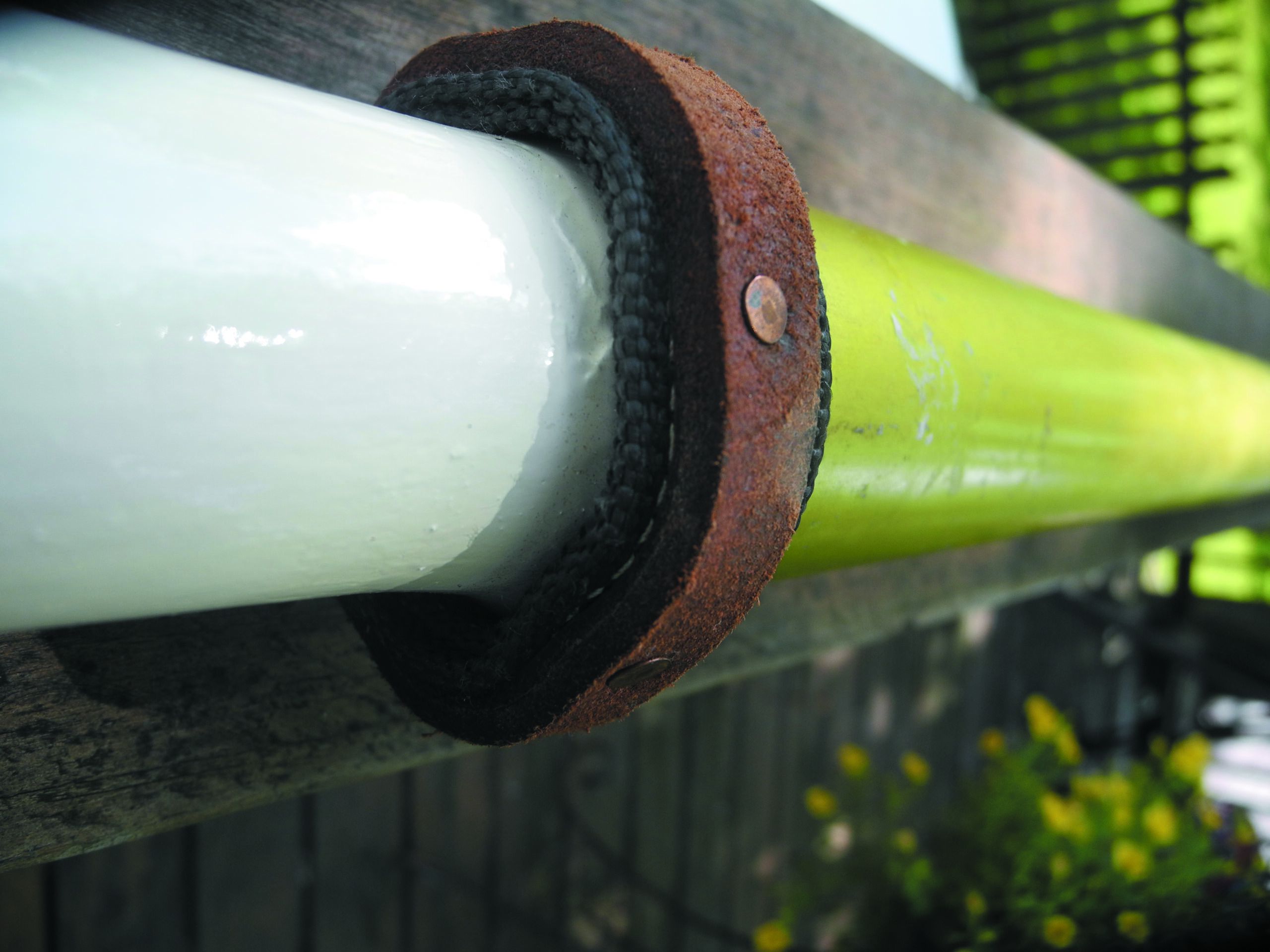
Over in my scrap tubing collection resided a useful piece of anodized aluminum tubing, that was once part of the lower section of a broken windsurfer spar. It had an inside diameter that was just a couple of millimeters larger than the outside diameter of the new sculling oar.
I cut a piece that easily slid over the shaft splice and created a belt-and-suspenders reinforcement for the scarf. The tube section also provided chafe protection for the portion of the oar that made contact with the wooden sculling notch mounted on the outboard bracket.
Sanding and Strengthening
When the blade-to-blade scarf had cured, I planed and sanded the junction area, so the contour was smooth and even. Finally, the joint was strengthened by laminating bidirectional roving and 10-ounce boat cloth to each side of the extended blade. The next morning, I mixed a batch of low-density West 407 filler and 105/205 resin and stirred it up as a final fairing putty. After sanding the sculling oar, it was painted with Interlux 404/414 epoxy primer and Brightside.
The traditional notch in the transom, seen on Bahamian dinghies and other craft set up for sculling was not a feasible solution. But a piece of 3/4-inch marine plywood was notched for the sculling oar and affixed to the outboard bracket with two 3/8-inch machine screws, washers and wingnuts. This allowed for a quick transition to Torqeedo power when and if Andy had enough exercise or found an uncooperative head wind.
Sculling Tips
Sculling, like rowing, is easy to learn but takes some time to become proficient. The major difference is when rowing, the oar blade enters the water at approximately a 45 degree angle to the centerline of the boat at the “catch” that initiates the drive portion of the stroke. It passes though about 90 degrees to the “extraction” point. As the blade is lifted out of the water and feathered through the “recovery”, the cycle is completed. This feathering motion is initiated by twisting the wrist downward and turning the blade parallel to the surface of the water. It’s a technique that improves a rower’s efficiency, especially when pulling to windward. It’s also a technique at the heart of sculling.
Sculling involves a figure-8 push/pull continuous motion. The handle of the long stern sculling oar is moved left and right across the vessel’s centerline, but it is not lifted from the water, and the recovery phase of the rowing stroke is eliminated. This motion seldom makes more than a 20-degree angle with the centerline and the figure-8 pattern involves a push/pull arm motion. Twisting the wrist results in a more of a propeller-like push against the water. During these continuous push/pull transitions, the force generated by the oar blade’s motion is transmitted up the shaft and into the bracket, causing the boat to move forward.


