

Well intentioned friends and relatives often make comments along the lines of, “Aren’t you scared of being out on the ocean, all alone, in a small boat?” to which I invariably respond, “No, with modern navigation, communications, weather forecasting and reliable engines, the risks that prior generations of sailors faced have been greatly reduced.” Two significant risk areas largely remain beyond the reach of modern technology, however: lightning and the risk of an onboard electrical fire. Onboard electrical fire risk has increased over the decades due to a significant increase in the complexity of boat systems, which has increased further still in recent years due to higher capacity batteries.
When you’re on a small boat, there is nowhere to run in the event of a fire. While fire extinguishing systems can help, clearly the priority needs to be to take every possible step to avoid a fire occurring in the first place. According to an analysis of Boat US insurance claim data, over 50 percent of onboard fires arise from electrical failures, either in the AC or DC systems, with engine areas and battery areas particularly vulnerable locations.
Maintenance Is Key to Prevent Fires
As children, we were invariably taught to respect the potentially lethal nature of 110 V or 220 V AC systems. Conversely, childhood experiences taught us to think of low voltage DC systems as perfectly safe, encouraging many boaters to neglect or even experiment with their boat’s (12 or 24 V) DC system, innocent to the fact that the current carrying capacity of modern batteries and alternators is far greater than any childhood toy. That capacity translates into the capacity to create heat and ignite a fire. Maintaining your boat’s electrical system, especially on older boats, is therefore a priority safety consideration.
Another key consideration is that your boat’s electrical system is subject to an extraordinarily aggressive environment. That includes heat, UV, humidity, salt, vibration and potentially direct exposure to water, petroleum products, lightning surges and pests. This is a far more aggressive environment than any domestic system and is comparable to a more extreme industrial environment.
The challenge for us boaters is to maintain a reliable electrical system, in this environment, without incurring the huge costs and redundancy that an industrial application would consider a routine necessity. That does, however, require some vigilance on our part.
Auditing Your Electrical System
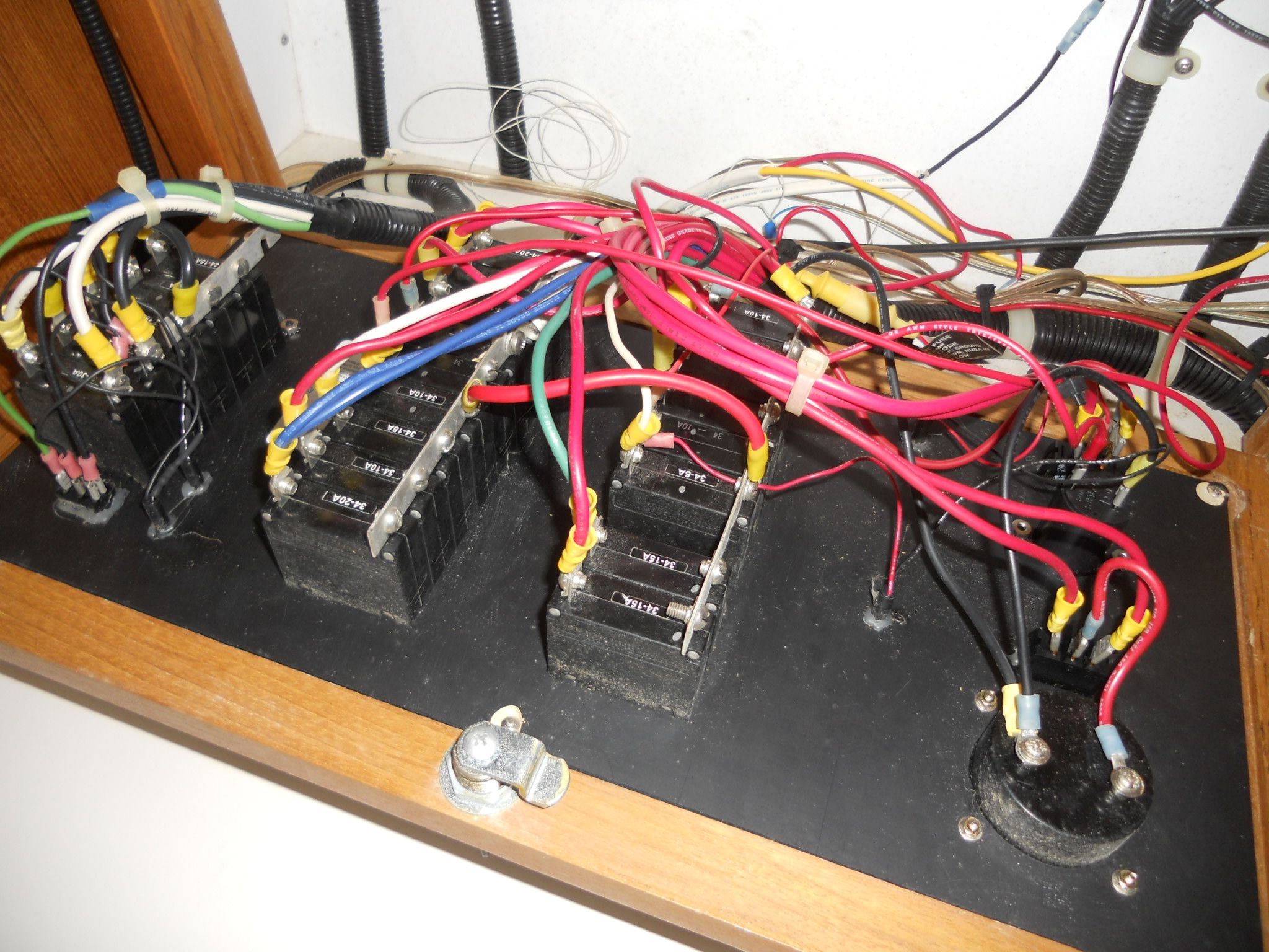
Unless you are lucky enough to have owned your boat from new, you will likely have a boat where previous owners have dabbled with the boat’s electrical system with multiple, amateur-installed additions and modifications of uncertain quality. Even if any upgrades were professionally installed, to all relevant codes, the life expectancy of cabling and terminations in the marine environment is limited. The life expectancy of household wiring systems is often quoted in the 50-to-70-year range, and given the hostile nature of the marine environment, sailors may need to think in terms of a 25-year life expectancy.
You may not feel inclined to incur the huge cost and disruption involved in replacing the entirety of your electrical system, however, simply because some expert says so. The alternative is to start replacing individual circuits, one at a time, as opportunity and/or need arises, in much the same way as we progressively change and upgrade our wardrobe or redecorate our home, one room at a time. An otherwise daunting task becomes manageable that way.
Where To Begin
Start by undertaking a good audit of your electrical wiring system, approached in a methodical manner, step by step. For my own system—a 1975 production boat, with a history of multiple owners— I approached this by examining each individual circuit, one at a time, starting with the AC circuits; then the primary DC circuits (the 2AWG or larger cables to battery, panel, engine etc.); then the lower power DC circuits (fridge, water pump, lights etc.) and; finally, by examining the low current instrument cables.
Circuits Are Circular
Bear in mind that, by definition, a circuit means circular, which includes both the positive and negative sides—or, in the case of AC, the live and the neutral sides—as both are equally important. Anecdotally, when I hear boaters discuss their electrical system, they often only focus on the positive and overlook the negative (or return) side. This is, therefore, where problems often hide, as that part of the circuit is more likely to be the subject of neglect.
When To Call a Pro
I should add, at this point, that ABYC regulations cover both DC and AC systems. AC systems may also be subject to national or local jurisdictional regulations, for good reason, as you are dealing with the risk of both fire and shock. While you have every reason to want to understand your boat’s AC system, therefore, you might—and you may be required to—conclude that you need to call in a licensed electrical professional for any such work.
Audit’s Goal
Your goal, in such an audit, should be to examine every individual circuit, end to end. If you have sections of cable run that are completely inaccessible—maybe through a cabinet before the original boat manufacturer glassed in an additional section—this might be difficult to achieve. That leaves you with two options e.g. either: replace the circuit, routing it somewhere that can be traced—which is what I did—or; create some suitably large inspection hatches to examine the wiring in situ. In an older boat you may also find that multiple cables are bundled together with insulating tape and, if you do, you have to unwrap and clean up the whole sticky mess, just to see what you have hiding underneath.
What To Look For in an Electrical Audit?
1. Check for Marine Grade Wiring

Firstly, check that the wiring is marine grade, as these have tougher outer sheaths—that resist abrasion, saltwater corrosion, UV rays, petroleum products and temperature extremes—and have copper conductors tinned with solder—to resist corrosion. Depending on what you are comparing it to, they may also be more flexible, making it easier to route through the confined spaces of a boat.
If you find that welding wire has been used for the large DC cables, as seems to be a common practice, you need to view that as an acute fire risk and replace them, as the insulation can dissolve on exposure to diesel fuel. Household or automotive grade cabling is less grave of a sin, but I would also always replace these, as the insulation is not up to marine standards and the conductors untinned or less flexible.
Note: All marine-rated cables should have an insulation temperature rating printed on the outer sheaf, of 105 C/221 F—although European ratings may be lower. If a cable does not have such a temperature rating, assume it is not marine grade and replace it. When replacing cables, you also want to follow ABYC recommended color coding.
2. Check Wire Size

Secondly, you are checking that the cable is appropriately sized. To give an extreme example, if you have an undersized cable running between the start battery and the starter motor, the starter motor may still turnover, but the cable could potentially glow red hot and even melt the insulation, starting a fire. In the article “Lithium Batteries for Small Boats: Troubleshooting,” we discussed the importance of cable sizing and said that volt drop—which translates into heat—is either “Dangerous,” “Frustrating” or “Acceptable.” This would be an example of a volt drop in the dangerous category, and the cable needs to be replaced immediately.
Good practice, therefore, is to regularly touch all of your cables to determine whether they are running uncharacteristically warm and investigate accordingly. While not obviously a fire hazard, an example of a frustrating volt drop might be a digital device, such as a DC-to-DC converter, not receiving sufficient volts to operate to specification.
3. Check Connections
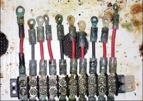
Thirdly, volt drop, and therefore heat, can also arise from corroded or lose terminations. In your audit, therefore, you are also looking for loose terminal screw connections and/or corroded connections—especially if you had any untinned, steel or aluminum terminals. Even if your cable strands are tinned, it’s very possible that the wiring lugs or terminals were not, necessitating either replacement or a periodic cleaning with a small—always brass and never steel—wire brush and/or fine sandpaper. After cleaning or replacement, I apply silicon spray—which I tell myself slows corrosion—and repeat at least annually.
We can also test for volt drop with a simple electrical multimeter, the two most obvious tests being resistance (impedance) and voltage readings. Examples are given in the insert.
The simplest use of the ohmmeter is a continuity test. Touch the two probes together and the resistance should drop to zero—and depending on the model, a beeper might sound— indicating zero ohms, and therefore a good passage for electric current. Now try the same on part of a—disconnected—circuit. Provided that the cable and connections are good, you should still get a very low reading, probably in the thousands of an ohm—online wire resistance tables will tell you the exact number to expect. If you get a materially higher reading, that’s indicative of something wrong, such as a cut cable or poor connection. Another test is a test to ground. With everything disconnected, place one probe on a positive cable, the other on a convenient ground—engine, battery terminal or cable—and the ohmmeter should give an infinite reading (e.g. no passage for electric current). If there is a reading, this may be indicative of a short and you need to investigate further. You can also do the test on non-digital equipment, such as on a windlass. The number itself will not tell you much—without some complex calculations about the motor windings—but if the number were to change over time, that would indicate something to investigate. My preference, however, is always a voltage drop test. As an example, you are concerned that the refrigerator is underperforming and you therefore take a series of voltage readings, such as: The voltage at the battery terminals is at 13.0 V; at the main isolator 12.7 V; at the circuit breaker panel 12.4 V; and at the fridge 12.2 V (when not cycling) or 11.6 V (when cycling). How to interpret such information? Working backwards, when the fridge is not cycling, you lose only 0.2 V in the long cables (from panel to galley) but 0.8 V when cycling. Why? Electrical losses increase with the square of the current, so some increase in volt drop is to be expected. (For more info on voltage drop, see “Lithium Batteries for Small Boats: Troubleshooting.”) Your fridge compressor probably consumes something in the order of 7 amps, but a 0.8 V drop is quite high. What to do? The obvious first and simple step is to clean up all terminals and check to see if the delivered voltage level improves. If that doesn’t help, check the cable sizing against volt drop tables, remembering that the distance includes both positive and negative cables. Remember also that the wire sizing and volt drop tables are simply a guide, not a requirement. If all the terminals are good and the cable size consistent with the table, you can still consider upgrading the cables to the next size up, to reduce voltage loss. On my boat, when I replace cables, I now habitually go one or two sizes higher, as the additional cost of the larger cables is often not significant. However, you might also want to examine the other end of the system and ask why you are losing 0.6 V between battery and panel? Are those cables undersized, or are terminals corroded? If you had other loads being served at the same time—which would act to pull down the voltage—switch those off and see if the voltage levels improve. Step by step, therefore, you get to know and upgrade your system, progressively eliminating all weak points and able to detect, early on, any signs of future trouble.Resistance Test

Voltage Test
Clean Terminals and Check Volt Drop Tables
4. Check Insulation
The fourth step in our wiring audit is to look for any evidence of deteriorated insulation, such as from chafing—potentially from vibration or abrasion—or chemical contamination, or worse, smoldering from excessive current arising from a full or partial short circuit. Needless to say, if you find such damage, you again replace the entire length of cable.
Next, check that all cables are adequately supported and protected, thereby limiting potential future chafing. As for the use of conduit, it is necessary in locations where there is the risk of physical damage or chafing (such as in the mast) but, otherwise, my preferred practice is to leave the cabling in an open cable run, visible for constant examination.
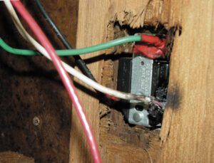
Next, look for any butt connections—crimped or, worse, wires wrapped under insulating tape. You will be very lucky if you find none of those. The rule on my boat is zero such connections and when I have found them, I replaced the entire circuit with a continuous length of the correct cable. There is no exception for the connection of equipment that comes with short pigtails and these need to be connected by means of a mounted terminal block—which also has the benefit of being a good place to conduct voltage tests.
Electrical Protection
The final element of your electrical system audit is to critically evaluate whether all circuits are adequately protected. As we said earlier, modern alternators and batteries are capable of producing very high currents, so we need to ensure that any excess current is cut off as quickly as possible, by the use of an electrical protection device—either circuit breaker or fuse. Otherwise, the excess current will generate excess heat and risk starting a fire.
A key fact to understand, however, is that the smaller the wire rating, the less capacity it has to carry current without overheating. Logic therefore dictates that both heavy and smaller wires are capable of igniting a fire and are therefore both equally deserving our attention.
Read the Regs
Please note, however, that electrical protection is a complex subject with a series of exceptions and qualifications. Given this complexity, please therefore view these few observations as a simple, high-level introduction, sufficient only for you to be encouraged to read the relevant ABYC codes and/or to undertake the necessary studies.
Circuit Breakers and Fuses
There are differences between circuit breakers and fuses and between different types of circuit breaker and fuse. Specifications are important—a 15 amp circuit breaker might swiftly close a 50 amp fault current but not a high current dead short—for which you need a high amperage interrupt capability or “high AIC” fuse. AC circuit protection is another whole subject, as is the start battery to start motor protection.
Moreover, we need to recognize the difference between “short circuit protection”—where the wire is appropriately sized, but a high current event occurs, briefly, before the protection cuts the circuit—and “overload protection.” Overload protection is more complex. An example might be wiring to a pump motor that’s rotor is jammed or a receptacle for plug-in devices—with too many devices plugged in. In such a case, sustained overload can arise, sufficient to cause the wiring to overheat but insufficient to trip the protection.
Short Circuit Protection
To return to the simpler case of short circuit protection, the protection needs to be sized according to the allowed current carrying capacity of the conductor—“ampacity”—which is provided by an ABYC table. The table not only considers size but factors such as location. If the rating of the cable is larger than the protection required for a piece of equipment, you protect for the lower case. If one device is protecting multiple circuits, you still protect for the lower case—except where the device feeds a subsidiary panel, from where each sub-circuit has its own protection, in which case it is protecting the cable to that panel.
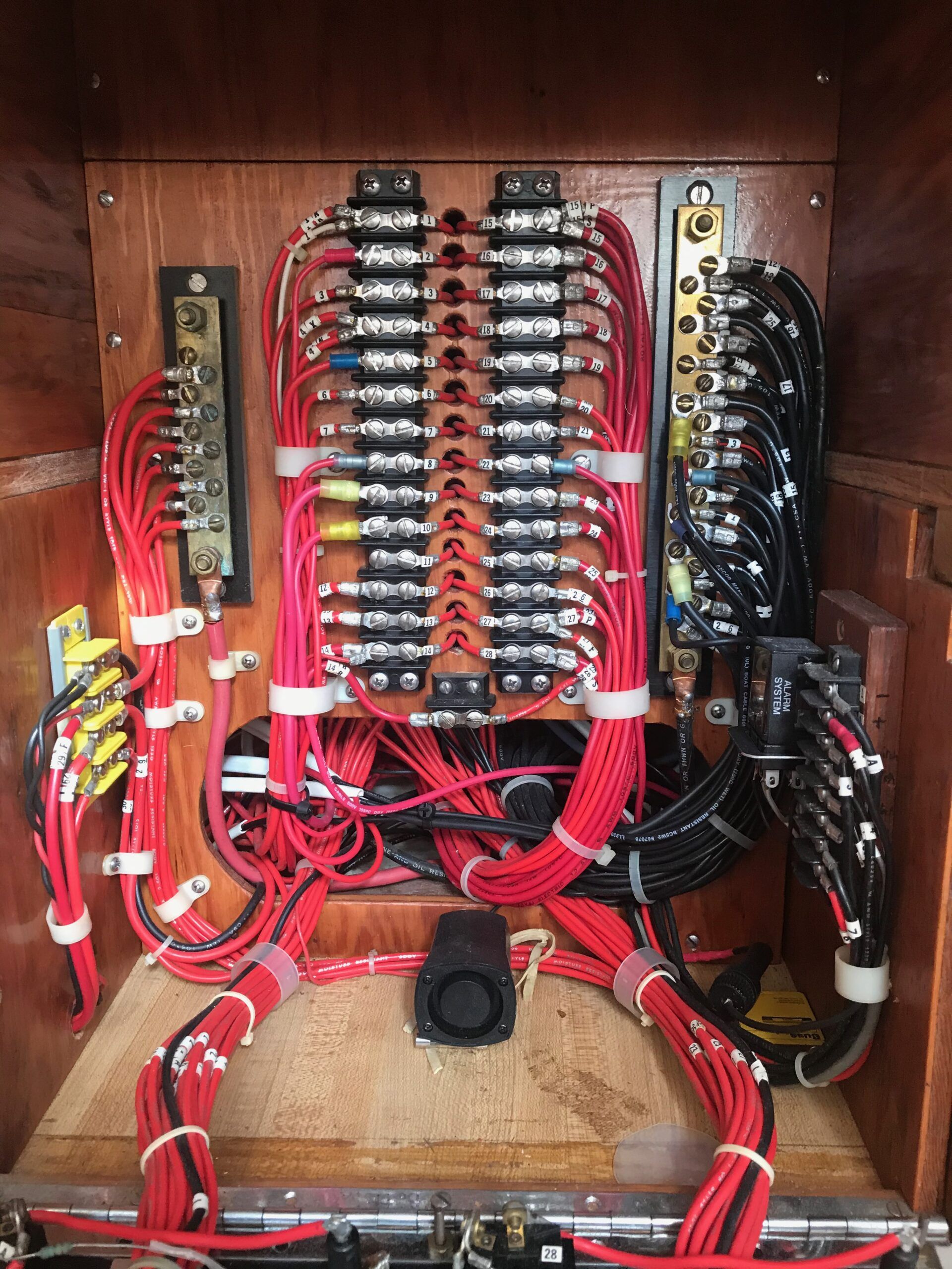
Electrical Switch Panel
You may ask about the electrical switch panel itself. In my case, I replaced it with a modern circuit breaker panel but derated the standard 15 amp breakers with lower (5 and 10 amp) rated breakers, where appropriate. As we hinted at earlier, circuit breakers and fuses have their own characteristics, and I like the combination of circuit breakers—lightning-fast response to a short circuit—and fuses—available in a wider range of sizes. I therefore have circuit breakers protecting a group of circuits—such as cabin lights—feeding a busbar, from where each individual circuit is protected by its own fuse. Of course, non-panel loads, such as the bilge pump and windlass, have their own separate arrangements.
Other Equipment
So much has been written about lead acid battery maintenance that I will add nothing to the subject here. As to the family of lithium-ion batteries, we have not really had them around long enough to say much about any long-term maintenance issues, but they do have their own fire safety issues, which are addressed in a separate insert.
LiFePo4 is characterized by being the most chemically stable and least prone to the risk of a thermal event. They are therefore preferred for marine house bank applications but do not always lend themselves to portable applications, such as electric propulsion or tools. You are therefore likely to have several types of lithium-ion battery on board your boat. A thermal runaway event is a dangerous, self-sustaining, chemical chain reaction, in which the heat generated exceeds the battery’s ability to dissipate that heat. As the temperature builds, the chemical process accelerates, thereby generating additional heat. The high temperatures, generated that way, lead to the degradation of the battery and the release of inflammable gases, which are ignited, further accelerating the run-away nature of the event. Once started, such events are hard to control and notoriously difficult to extinguish. Such an event can occur in all types, arising from a manufacturing defect or abuse. Abuse might be in the form of mechanical, thermal or electrical abuse, all potentially leading to an internal short-circuit and a run-away event. In general, as a battery gets older, its vulnerability to such events increases. An example of physical abuse might be being dropped or punctured, and an example of thermal abuse would be high ambient temperatures. Electrically, over-charging can cause internal shorts and electrolyte decomposition, leading to thermal runaway. Over-discharging (especially repeated over-discharging) is a different process but can similarly lead to decomposition and failure. Battery management systems (BMS) are promoted as managing such risks, but not all BMS systems are created equal. Many of the early lithium-ion batteries had minimal functionality and might be more accurately described as a basic protection circuit. Even a more recent, more sophisticated BMS may not be able to respond to a mechanical or thermal abuse event, as it may itself be damaged. The primary focus of a BMS is, therefore, to manage electrical issues such as cell balancing; short-circuit protection (although you may not want to rely on that capability); survival from a reverse polarity event and; battery to battery communication—should you have batteries in series or in parallel, but that does not necessarily address all balancing issues because a single, bigger battery is always preferable. Statistics suggest that thermal abuse is a common problem, but electric over discharging abuse is also a particular problem, as the battery may not have the available power to supply the BMS—depending on where the low voltage cut off point is set at. Firstly, acknowledge that lead-acid remains the superior and safer technology for high current loads, such as engine starter motor operation. With lithium-ion applications, the obvious preference should always be for the safer LiFePo4 chemistry, if the application makes that possible. Secondly, regardless of battery type, you first need to accept your own responsibilities. All lithium-ion batteries behave very different from lead acid batteries and the risks from abuse are potentially far more serious. Act prudently! Thereafter, you need to view the BMS as an essential safety feature, potentially protecting you and your crew from a dangerous thermal run-away event. You therefore absolutely should buy from a reputable manufacturer or importer, who gives you detailed explanations on the specification of their units and its BMS, together with comprehensive test data from simulated failures, diligently following all technical guidance and the new ABYC E-13. Understand, also, that if you seek to build your own multi-cell or multi-battery system and/or repurpose a used battery from a different application (such as an E-V), or use a charger from a different application, you are greatly increasing the risks involved. Many of the reported fires (on land), arise from such modified battery systems or conversion kits.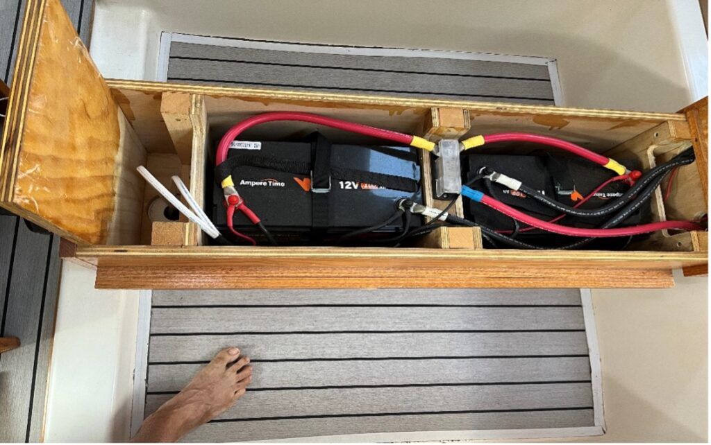
Thermal Runaway Event
Battery Abuse
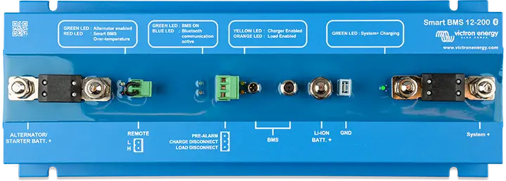
Battery Management Systems
What Can the Average Boater Do About Minimizing These Risks?
As to the main equipment loads on a vessel, technology upgrades such as LED lighting, improved functionality of navigation equipment, etc., usually dictates when we change that equipment, rather than any electrical consideration. I would add, however, that I know of many serious cruisers that would happily return to the days when depth sounder, radar, GPS etc. were separate—and not integrated—systems, as this can provide greater reliability, especially in the case of a lightning strike. There is also an argument that the older systems were built more robustly and, provided there are no signs of electrical deterioration, you may want to keep it for as long as it continues to serve your needs.
How To Approach the Maintenance of Heavier Equipment, Such As Electrical Windlasses, Winches, Bow Thrusters etc.?
I would argue, again, that the electro-mechanical equipment manufactured a few decades ago is equal to and potentially better than that built today, so provided that you undertake the necessary scheduled maintenance—terminals, bushes, greasing etc.—and periodically examine the electrical components, you have every reason to keep it for as long as it serves your needs. A regular resistance or continuity test is helpful, too.
Of course, it is always important to provide the appropriate circuit protection, as such equipment likely has some of the longer cable runs on the boat, with the greater potential for unseen chafing or physical damage.


Thankfully, boat fires are rare events. So far, the only sailboat fires I have witnessed have come from the starter motor. The ABYC codes don’t require fuses or breakers on starters. When the rotor locks up, things get hot in a hurry. Usually alternators are also not fused.
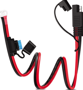
It’s not very expensive to add a high amperage fuse. Blue Sea makes a fuse holder the goes on the cable. I fused my starter at 300 amps and never had a nuisance trip on a 40 HP Yanmar 4JH2E.
Blue Sea Systems 5191 Fuse Block Terminal 30-300 AMP