

A sailboat’s steering system also plays a vital role in safety at sea. The failure of any key component can jeopardize boat handling and turn your easy-to-steer, well behaved old friend into an unguided missile. When such chaos grabs hold, it’s the emergency tiller that can save the day.
This close-up look at steering systems focuses on new and traditional ways to link the rudder and the helm, notes the importance of well-engineered hardware and delves into what’s going on with emergency steering alternatives. Our focus in this article is on steering system malfunctions, not rudder failures.
Background
Tiller steering is about as bulletproof a system as found on any modern sailboat. There are fewer components, easier access for inspection and certainly lower cost. This “keep it simple” approach has a lot to offer.
Unfortunately, larger boats require longer tillers and unless it’s a semi-balanced rudder, with ample surface area forward of the rudder stock, there’s no power-steering effect. That’s what gave rise to the old adage about needing “two men and a boy” to steer some sailboats. Hours spent on such a helm yield more pain than pleasure. The good news is most modern wheel steering systems can ease such a burden. So, despite the simplicity and reliability advantages that tiller steering has to offer, it’s rarely found on new cruising boats longer than 30 feet.
Wheel steering isn’t the holy grail and one system doesn’t fit all boat designs. It has some challenges all its own. One of them is how to link the helm and rudder on sailboats with center cockpits. Quite often, the space between is occupied by an engine room, owner’s cabin or both. This results in a maze-like pathway that must be traversed in order to link the wheel and the rudder. The way each designer/builder decides to bridge this gap helps define what system they use and how complicated, smooth spinning and reliable the steering becomes.
There are five generic approaches to turning the helmsperson’s rotary motion wheel input into an axial force exerted on the rudder. They are usually referred to as geared, cable/quadrant, drag link, torque tube or hydraulic steering.
Rack and Pinion
Early on, the bronze geared rack-and-pinion system scored a hit aboard aft cockpit sloops, yawls, schooners and ketches. This simple rack and pinion design relied on the wheel being placed close to the rudder and keeping the gears in tight alignment throughout the turning arc. This system was revered by some but deemed “hard-mouthed” by many.
Unfortunately, with age, the gears and shaft support bushings become worn and tight tolerances give way to gear teeth jumping over each other rather than affecting rudder angle changes. The cost of replacing custom castings can be prohibitive and many builders and boat owners of rack-and-pinion steered boats have switched to other systems.
PROS AND CONS OF STEERING TYPES
| STEERING TYPE | PROS | CONS | COMMENTS |
|---|---|---|---|
| RACK AND PINION | Rugged, proven design | Increased friction, no feedback | Watch for wear, friction |
| CABLE QUADRANT | Relatively simple design | Cables and sheave failure potential | Requires routine checks |
| CABLE IN CONDUIT | Simple installation | Increased friction, corrosion | Twin cable system is far superior |
| DRAG LINK | Robust system | Bearing corrosion is an issue | Good compromise for big boats |
| TORQUE TUBE | Popular on big boats | Bearing corrosion can be an issue | Check for friction, corrosion |
| HYDRAULIC | Easily routed through boat | No rudder feedback | Robust design, have backup pump |
| TILLER | Simple, instant feedback | Not suited for big boats | Easy to setup for windvane steering |
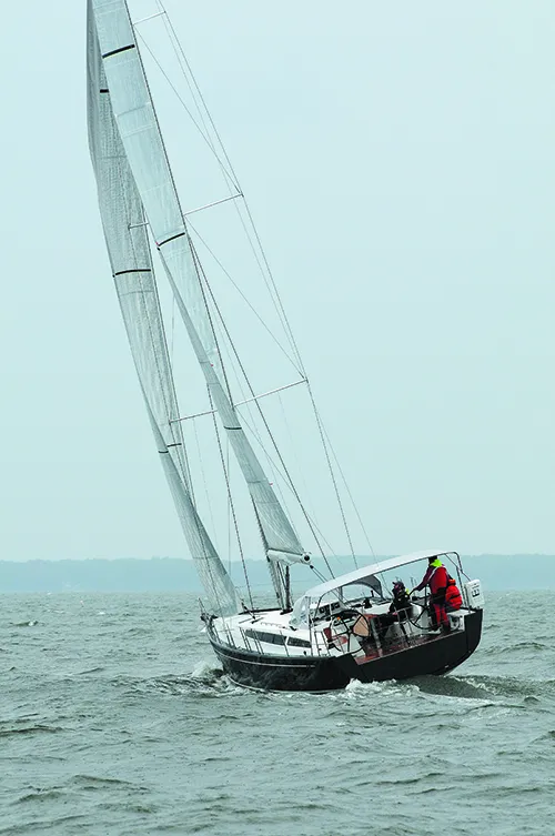
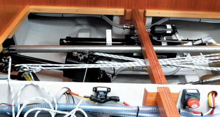
1. Twin rudders require a linkage to transmit steering forces from one rudder to another.

Cable/Quadrant
One of the most popular ways to connect the wheel and rudder is via a set of cables run through sheaves to a chain and sprocket attached to the steering wheel shaft. There are several major advantages to this approach and they include simplicity, excellent feedback and the relative simplicity of DIY repairs.
Such systems began to play a dominant role with the advent of fiber reinforced plastic (FRP) boatbuilding. The industry rallied toward this wire rope, “pull/pull” approach to changing rudder angle. It was augmented by the development of flexible, low stretch, 7×19 stainless steel wire. Edson refined the approach, adding better aligned bracket mounted bronze sheaves, easy to attach at cable turning points. These carefully placed lead pulleys (also called idler blocks), led the wire rope to the port and starboard sides of the quadrant or disk drive. At the opposite end, both lengths of cable attached to a short piece of stainless steel, bicycle-like chain that engaged the wheel shaft sprocket.
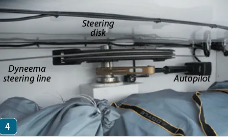
Unfortunately, our recent boat show surveys and sea trials show that many emergency tiller designs are worse than the automotive industry’s idea of a spare tire. Those faced with a steering system failure at sea need an easy-to-install, efficient steering alternative. Many approaches to emergency steering have become more of an afterthought rather than a 24/7 ocean usable backup system. Ideally, we want hardware that solidly attaches to the rudder stock, offers enough leverage to easily affect rudder angle changes in all weather conditions, and situates the helmsperson in a safe place with good visibility.
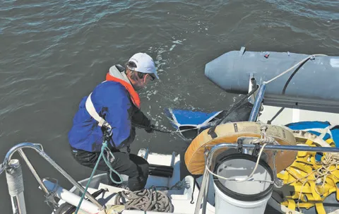
1. Adding block and tackle emergency steering to a crowded compartment located under the aft cabin berth makes boat handling difficult for a helmsperson who can’t see where they are going.
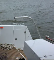
2. The main problem with the “bent pipe” emergency tiller approach is that there’s not enough lever length to handle steering loads and all too often there’s a poorly fitted connection between pipe and the head of the rudder stock.
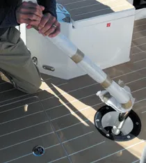
3. We found ill-fitting, wobbly pipe extensions, weak connections with too little leverage, that in some cases left the helmsperson with little or no visibility at all.
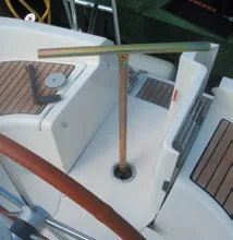
4. Some emergency tillers are so inefficient that the helmsperson, rather than the vessel, are being steered. As wind and wave action increases, course control becomes a losing battle. This wobbly T-fitting is misaligned so that it rubs against the access hole. A T-type emergency tillers can be efficient as long as the person at the helm retains good visibility and some comfort. This setup meets the former criteria.
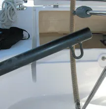
5. Some emergency tillers provide fittings for two lines to be run to cockpit winches on either side of the boat. This requires two people with winch handles to be available on a 24/7 basis. In many cases, a short emergency tiller is mandated due to cockpit tables, binnacles and running rigging that intrude on a longer tillers swing arc. Connection points for lines to winches can add more steering power but the tiller’s connection to the head of the rudder stock must be solid.
In most cases, this hardware was built into the pedestal base directly below the binnacle. The wheel itself is keyed to the shaft and as it turns in one direction or the other, cable tension causes rudder deflection and the boat steers toward where the wheel has been rotated. Inside the pedestal, the chain is swaged, clamped or nicopressed to the wire steering cables.
Common Problems and Wear Points
Bushings support the wheel shaft and a set of carefully aligned blocks at the base of the pedestal redirect the cable run from the vertical into a horizontal plane. This rather simple, yet ingenious solution, fit the bill for decades, especially when helms and rudder stocks were in close proximity. However, the longer the run and the more obstacles in the way, the more cable length and pulleys had to be added and friction, stretch and chafe increased.
Advocates still say that no other steering system, other than the tiller, offers as much feel. These cable-over-sheaves systems are alive and well, even among performance oriented sailors who have shown a growing interest in using high modulus fiber rope instead of wire. But many have learned the hard way that although the tensile strength and resistance to elongation of HMPE fibers is very impressive, great care must be taken to eliminate chafe and maintain careful alignment throughout the arc of the rudder’s swing.

Cable in Conduit
Cable steering also has an alternate genre that’s seen on both multihulls and monohulls. There are two iterations of this cable-inside-a-conduit approach. The main advantage with this alternative goes to boat builders who can link the helm and the rudder with far fewer labor hours involved in the process.
The push/pull version is akin to a throttle or shift cable on steroids. It turns the rotary motion of the wheel into a push or pull axial force that turns the rudder stock. These single cable system systems were first used on outboard motors and incorporated a bidirectional, rack-and-pinion link to the wheel. The appeal of this approach includes an ease of installation, the elimination of the need for turning blocks and the convenience with which a single cable could be snaked around obstacles.
Unfortunately, when the cable bends are too tight and it’s not secured to the hull’s inner skin, the result is increased friction, poor feedback, and when used on larger sailboats with higher steering loads, the frequency of stripped rack-and-pinion gears grows much higher, especially in the push phase of cable motion.
The dual cable-in-conduit alternative tends to eliminate this problem. It combines a chain and cable pedestal with a transition to twin cable-in-conduit runs that snake through the bilge. It replaces the single push/pull cable with a system that handles turning in either direction through cable tension. This type of steering eliminates the push component, the Achilles heel of the single cable system.
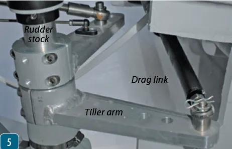
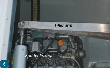
Drag Link
A drag link steering system uses rigid tubes, rods and levers to affect the push/pull force needed to change rudder angle. The drag link steering system’s pedestal supports a wheel connected to a pinion shaft that engages a bronze rack gear. It delivers wheel-induced torque to a vertical tube running down the center of the pedestal. It’s connected to a lever located just below the base of the pedestal.
The rotary motion actuates the lever and causes movement of the tubular linkage connecting the wheel to another small lever attached to the rudder stock. The geometry of this push-pull exchange is very important and components must be carefully aligned. Slight misalignment is handled by the ball joints in the tube end fittings. But the better the alignment, the more efficient the steering will be. It’s important to keep the ball joints lubricated (greased) and regularly pump some grease into the zerk fitting at the bottom pedestal bearing.
Drag link steering systems deliver smooth, sensitive steering control. But the pedestal does contain more mechanical linkage and one of the major concerns is making sure that the manufacturer’s recommendations about rudder stops are adhered to. If not, when the wheel is intentionally or unintentionally released while going astern, the rudder will slam over to one side or the other and the linkage can be seriously damaged. To a greater or lesser extent, this goes for all wheel steering systems and most manufacturers provide specific details about required rudder stops.
Torque Tube
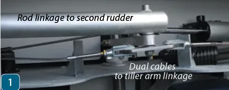
On one hand, this is the most complex approach to sailboat steering, but on the other, when skillfully installed, it can span half a boat length and still provide smooth efficient helm control. One of the key considerations is that there are lots of dissimilar metals combined in housings, bearings and seals, bevel gears, tubing, universal joints and reduction gears. And despite the fact that the system is installed below deck, ambient conditions in the bilge are moist enough to add some corrosion control concerns.
Like all other steering systems, the torque tube approach is all about delivering a 180-degree reversible, axial steering force to the rudder. To do so, the wheel and the rudder are connected via a series of universal joints, torque tubes and specialized bevel gears.
This tube rotation link up between the helm and the rudder requires a set of pillow block bearing supports for each tube, universal joints to interconnect the tubes, and secure anchor points on bulkheads, custom brackets or the hull itself. A reduction gear, placed near the rudder stock, converts tube torque into the axial movement of a short lever linked to the rudder stock. This short lever is a mini tiller and a small amount of throw (movement) results in a larger amount of rudder deflection.
Installation and Load Considerations
Unfortunately, with less leverage there’s a big uptick in the force needed to execute the movement. Not only does the reduction gear create some serious output force, but the base that supports the hardware must be up to the task of handling these steering loads. Momentary peaks in rudder surface pressure, induced by sea state, cause loads in the steering system to spike. The bottom line is that the mounting bases and bracketing need to be up to the challenge.
Those with a Whitlock/Lewmar Mamba system can greatly extend the life of the hardware by following the manufacturer’s maintenance guidelines and keeping seawater away from bevel gear housing and the reduction gear. Also, use a magnet to locate ferrous metal components and regularly spray them with a corrosion protectant such as CRC Heavy Duty Corrosion Inhibitor.
Hydraulic Systems
Powerboaters hold hydraulic steering systems in high regard, partly because of their reliability and partly because rudder feedback is of little desire. Sailors, on the other hand, appreciate the “feel” of the helm and put that feedback to use in the sail trimming process. Consequently, sailors see steering via pumping hydraulic fluid to a piston ram as best suited to an autopilot rather than a helmsperson.
The upsides of hydraulic steering, however, includes the ease with which a flexible hose can be snaked through the bilge, from the wheel to the rudder. And there’s some logic to the idea that what works on a bulldozer is certainly rugged enough to handle things on a sailboat. Leaks and pump/ram problems are usually noticed early when steering begins to get a little spongy. In short, it’s a good way to transfer force but numb when it comes to useful feedback.
Conclusion
Although there’s no perfect wheel steering system, we do like and recommend traditional pull/pull wire cable with traditional sheaves. We also favor meticulously installed drag link and torque tube systems as long as the skipper recognizes the need to carry out periodic maintenance and watch out for corrosion related problems.
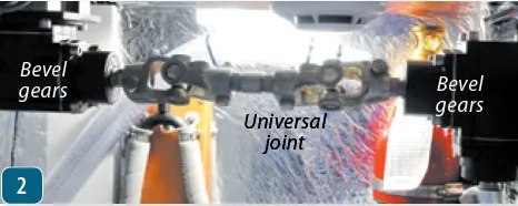
Some designers and builders seem to have greater faith in long-term system reliability and give too little attention to emergency steering systems. All too often, the manual override for the autopilot is the go-to emergency steering plan. We found that many sailboats with emergency tillers also flunked the emergency steering test. These so-called emergency tillers were often ill-fitting, unwilling to stay attached to the head of the rudder stock or were so hard to operate that they made steering in a seaway all but impossible.
Related posts: “Dealing with a Broken Idler Pulley on the High Seas“
This was published on 24 February 2020 and has been updated.


Great Article covering an item that is often overlooked, potentially at great cost. Some examples would have been really beneficial, so as to make the boat buyer a little wiser in the process.
There is a “#7018 Sailboat lock valve” made by Kobelt that allows rudder feedback and feel with hydraulic steering. Just move the lever to turn the bypass option off or on.
https://www.kobelt.com/docs/default-source/product-spec-sheets/7018-spec-sheet-(2016)
The sailboat’s rudder was one of its target structures; its engines were hidden beneath the hull. Every time the boat passes through the waves, the rudder creates friction in one direction and changes the direction of the boat.
Left out my Edson worm gear steering system. My problem with the system is when I am in reverse and get a head of steam going, the force on my large rudder kind of makes it real hard to turn the wheel. I have a Roberts steel 36 footer.
The article conflates a balanced rudder with a balanced sail plan. A serious misconception. A balanced rudder, as with a wheel, can hide an unbalanced sail plan and poor sail trim. I sailed a modified full keel boat many thousands of ocean miles with a tiller to a barn door rudder on a full skeg. Rudder definitely not balanced. Balancing the boat: sail center of effort to hull center of resistance, resulted in a neutral helm. This does take fussing with rig and sail trim, i.e. sailing. Then dial in a few degrees of weather helm with the main traveler for ‘feel’ and safety.