In “Lithium Batteries for Small Boats” we looked at some of the less frequently discussed differences between lead acid and LiFePO4 batteries. In “Lithium Batteries for Small Boats: Install Guide” we discussed how best to configure the new system, with a focus on the necessary equipment and wiring changes. In this article, we look at how I organized my own upgrade, the practical issues I encountered, how much it cost and what might I have done differently?
I should start by saying that my boat is nearly fifty years old. When I first purchased it, I found a rat’s nest of wiring, with many dead ended circuits, poor connections, non-marine grade wiring, poor fusing etc. The point of mentioning that is that I tidied all that up, long before looking to upgrade to LiFePO4. If you haven’t previously undertaken such a review of your boat’s legacy electrical system, I encourage you to do so, and to correct any issues before you start a LiFePO4 conversion.
Tidy Existing Wiring
Even so, I was conscious that my existing wiring was not entirely good practice. As an example, it was once common practice to make multiple connections to both the +ve (positive) and -ve (negative) battery terminals. Even if I had been minded to continue that practice, the LiFePO4 battery came with simple M8 terminals facilitating only a single connection. On the new +ve (positive) side, I therefore made a single short connection to the new Class T fuse and from there to a heavy-duty busbar. On the -ve (negative) side, I made a similar, single, short connection to the Battery Monitor shunt and from there to a second, similarly sized busbar. From the two busbars all external connections are made.

Introducing those busbars tidied everything up, but they do require some space, so a key consideration is to plan your physical layout. You also need to find a well-ventilated location for the DC-to-DC converter, preferably close to the two batteries (to minimize cable runs).
With the configuration laid out in “Lithium Batteries for Small Boats: Install Guide” I assumed that no changes would be necessary to the alternator, regulator, starter motor or start battery but I was naively optimistic in that regard, as we discuss later.
Equipment Selection
As to the selection of equipment, I went with Blue Sea for the busbars and Class T fuse, and Ancor for all the cables.
My existing smart charger was a ProMariner ProNautic 1240P (40 amp) and it had suitable LiFePO4 settings, so there was no reason to consider replacing this.
For the DC-to-DC converter, I considered both Sterling Power and Victron. I have high regard for Victron, but to my disappointment, I learned that they do not offer a bi-directional DC-to-DC converter. Sterling Power do offer one, however, so I went with their unit. With that, it was logical to also select their Battery Monitor.
As to the new LiFePO4 battery, I would probably have bought a Sterling Power battery (to match the other equipment), but LiFePO4 is subject to HAZMAT shipping regulations, and I could not get a shipping quote from either the U.S. or the U.K. Consequently, I bought the only one available locally, which was a 12 V, 270 ah Eco-Worthy, LiFePO4 battery which has performed well.
First Test–Battery Not Fully Charging
Once all the equipment was installed and wired up, I got to test the equipment.
My first test was simply to confirm that both the smart charger and the DC-to-DC converter were able to fully charge the LiFePO4 battery. Those tests did not go to plan, however, as both switched out of bulk charging mode and into float mode, prematurely (with the battery only at a 50 percent state of charge or SOC).
Interestingly, my experience was not unique, in that I found various online comments about other LiFePO4 users having the same experience. No one online offered a good explanation, however the best was that the charger must be confused and to re-boot and try again later! With the assistance of the three technical departments, we examined possible causes and came up with three possible explanations:
- A battery fault was triggering a BMS response, that momentarily produces a voltage spike, which confuses the smart charger into believing that the battery SOC is higher than it is (considered the least likely explanation, as any such spike should be temporary, which means that the fault should clear itself);
- The charger was programmed or operating incorrectly, which proved to be part of the explanation, in the case of the ProMariner smart charger, which I had initially set to the wrong program;
- Volt drop between charging device and battery, which eventually was determined to be the primary cause, and a subject which deserves our close attention.
Volt Drop and Digital/Smart Chargers
Firstly, some electrical theory. “Losses” are determined by the P=I2R (or “I squared R”) formula, where current, I, is in amps; resistance, R is in ohms (for our limited purpose we can view the terms impedance and resistance as synonymous), and P is the power lost (primarily to heat) in watts. To reduce losses, we decrease resistance by installing fatter cables and by keeping cable runs as short as possible. We should also note that resistance (and therefore volt drop) can also arise from poor connections (such as might arise from corrosion or a loose terminal), so this is also an important consideration.
The other variable, current, is also important to understand, in that if you increase the current by 2X you increase power losses by 4X. Put simply, therefore, as you look to push more current through the system (which you are very likely to do with a LiFePO4 upgrade) you will need to also pay close attention to your existing cable sizes and the quality of your terminations.
To take a simple example, if at the battery end of a simple 12 volt circuit, you are delivering 10 amps (which is therefore 120 watts) and you have a 0.01 ohm loss, the power delivered would be 119 (120 minus 10 x 10 x 0.01) watts, giving you an output terminal voltage of 11.9 (119/10) volts. If you increase this to 40 amps, the power delivered would be 464 (480 minus 40 x 40 x 0.01) watts, giving you 11.6 (464/40) volts. So, the result of a 4X increase in current is that losses increase by 16X, and the voltage at the delivered end would drop from 11.9 to 11.6 volts.
How Digital “Smart” Charging Devices Operate
Now let’s apply that theory to how digital “smart” charging devices operate. In the absence of an external sensor, the unit will most likely be programed to presume that the voltage it is measuring at its own output terminals is the same as the battery voltage (i.e. it will presume a perfect circuit with no line losses). So, if your battery is actually at (say) 13.0 volts the smart charger might incorrectly conclude that its state of charge is 13.1 volts (0.1 volt line loss) or 13.4 volts (0.4 volt line loss), which is why a smart charger has the potential to prematurely switch into float mode.
Why is Volt Drop Less of a Concern with Lead Acid Battery Chargers?
You might think of voltage losses as immutable as Newton’s laws of motion, but they are never good. They are either: Acceptable; Frustrating or; Dangerous. Acceptable is where we acknowledge loss, but it doesn’t noticeably affect things. Frustrating is when you begin seeing noticeable effects in the system, such as batteries not charging or inverters turning off early; Dangerous is when the voltage loss is so significant that it is indicative of something seriously wrong. The probability is that your lead acid battery system operated, for years, in the “Acceptable” volt drop category, but the possibility is, when switching to a LiFePO4 system, that the same loss falls into the “Frustrating” category.
But why? Firstly, the voltage charging profile of lead acid is relatively steep, such that a 0.5 volt loss (and therefore a 0.5 volt error in the smart charger voltage reading) might be the difference between a 100 percent and a 90 percent SOC. The same error with LiFePO4 might be the difference between 100 percent and 70 percent SOC and therefore more significant. Secondly, on a LiFePO4 setting, smart chargers are in constant current mode close to a full charge, which means that losses do not taper off. With a lead acid battery there is a self-correcting component (as they have a higher internal resistance) as the current flow—and therefore losses—progressively decrease with SOC.
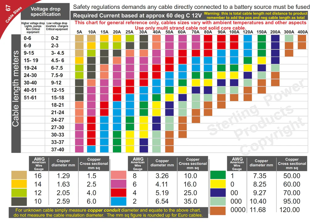
So, the primary conclusion from this is that you need to pay close attention to the size of your charging cables. You are probably all familiar with the West Marine cable sizing charts but the best I have come across is the one reproduced here (with the kind permission of Sterling Power). The first thing to note is that they place charging cables in the 3 percent category, rather than the traditional 10 percent category, where they have historically been placed, being viewed as a “non-critical” load.
Further Upgrades and Second Test
Given the results of my first test, I upgraded the cables on the “downstream” charging circuits between charging devices and the house battery to AWG 4 (from the previous AWG 8). I also examined my losses on the “upstream” alternator—start battery circuit (which feed the DC-to-DC converter input). The unit’s specification stated that it required an input of >13.8 V (in order to deliver full rating), which I was not delivering. That led me to replace both the old alternator and to upgrade those circuits (including going to a full 2/0 AWG from the alternator). Those changes allowed me to successfully deliver more than 14.0 V at the input side of the DC-to-DC converter.
With those changes, both the ProNautic Smart Charger and the Sterling DC-to-DC Converter charged the battery, with no repeat of the premature float condition that arose with the first test.
Parallel with these changes I added a 2 KW inverter and discarded my old gasoline generator set—a big weight saving. From that point onwards, I found that I could run power tools from the inverter, which illustrates my previous point that upgrading to LiFePO4 results in you finding new ways to use your electrical system. With the discarding of my generator set, however, I was relying more on my alternator, so I decided to further upgrade the system by adding a second DC-to-DC converter.
Equipment Sizing and Third Test
What does it mean when an alternator is rated at (say) 90 amps? To answer that question accurately you would need to ask your manufacturer for detailed performance curves, demonstrating how it operates at different temperatures, loads and RPM. In the absence of such a set of performance curves, you should at least recognize that its given “nameplate” rating is the very highest you will achieve under perfect conditions. Alternators are, of course, electro-mechanical devices, so performance is driven by more variables than digital electronic devices.
In “Lithium Batteries for Small Boats” we talked about how much battery capacity to buy, and we have also discussed what size of cables to buy but what size of DC-to-DC converter should you buy? If you install too large a DC-to-DC converter, the risk is that you will demand more from the alternator than it can comfortably deliver, although that may depend on the type of regulator you have any whether it contains any temperature sensing device. As a rule of thumb, the advice of Sterling Power was to not install a unit with a nameplate rating greater than 75 percent of the nameplate rating of the alternator.
My replacement alternator has a 90-amp rating, which means that advice should have led me to install a 70 amp or smaller unit. I took a slightly different approach, however, by installing a second 40 amp DC-to-DC converter, in parallel with the first, with one acting as a primary and the second to be switched on when engine was operating at 1,300 RPM or higher (the point I determined by testing). The alternative approach would have been to de-rate both units. The unit I purchased allows them to be programed for 85 percent or 60 percent performance, but I prefer this approach.
As you will appreciate, this information is manufacturer and boat specific, so as you plan your own system, I encourage you to ask your equipment manufacturers a series of such questions.
Finally, the Cost
Moonrise LiFePO4 Conversion Costs
Total Base Case Upgrades
Eco-Worthy, 280ah LiFePO4 Battery $499.99 $499.99
Sterling DC to DC Charger BB1240 $ 315.00 $ 315.00
Sterling DC to DC Charger BB1240 $ 315.00 $ 315.00
Sterling Battery Monitor - BM1 $ 95.00 $ 95.00
Terminations and fuses $346.22 $173.11 $173.11
Cabling $368.12 $69.94 $298.18
$1,939.33 $1,153.04 $786.29
The cost of the original project came to less than $1,200. The upgrades (primarily a second DC-to-DC converter and fatter cables) cost just under an additional $800, bringing my total to just under $2,000. Because this system should last at least ten years, the system is a vast improvement on what I had before, and I had got used to buying a set of three wet lead acid batteries every few years, for me the entire project was economically a winner.
Depending on your system, and if you find that you do not need to change out large cables, you might be able to replicate something similar for less than $1,000, which would be a bargain.
Of course, I also incurred other unrelated expenses at the same time, such as installing the correct alternator, more solar, an inverter, etc. but they might have been incurred at any time, and I do not view them as part of the conversion project.
Install Larger Cables
As to things I might have done differently, my only regret was to not install large cables from the beginning (I first installed new AWG 8 size cables for the charging circuits and then removed them, upgrading to AWG 4 cabling because of the volt drop issue). Other than that, I am very happy with my installation and would not change a thing. Moreover, my newly enhanced capacity means that I only need to think about charging the batteries once a week (recognizing I have also added to my solar capacity), whereas before it was every few days, which, alone is a huge improvement.
Conclusion
As to the take aways from this series of articles, the key messages should be that: LiFePO4 is now a mature technology for marine applications; It should not be confused with other types of Lithium-ion battery when considering the safety issue and; The average, competent sailboat owner should be able to organize their own, viable, inexpensive solution without cutting any corners.
Finally, let me say that I hope that you have found this series useful, and that it proves to be a better source of information for you than the confused advice I first found from on-line commentaries.
Lithium for Small Boats Series: