

This article focuses on sailboat LiFePO4 battery installations and the equipment and wiring changes we need to make to the electrical system in order to install the technology. “Lithium Batteries for Small Boats” considered some of the less frequently explored differences between LiFePO4 and lead acid battery systems and why those differences are important for a small boats electrical system. This series does, however, focus on the needs of sailboats. Super yachts, power boats, fishing vessels, commercial vessels etc. (and maybe sailboats bigger than 50 ft.) likely have different constraints and may therefore need to reach wholly different conclusions.
Note: I should be clear that these articles use 12 V terminology, but it is equally relevant to 24 V systems.
Lead Acid for Start Side, LiFePO4 for House Side
For the reasons explained in the “Lithium Batteries for Small Boats” it is generally not recommended to replace the start battery with LiFePO4, especially for diesel engine boats (with their higher compression ratio and higher starting current demands). Similarly, we explored the issues that arise with a conventional alternator directly charging a LiFePO4 battery.
This author, therefore, recommends that the simplest and most reliable approach is to retain a conventional lead acid battery and alternator on the start side and to introduce LiFePO4 only on the house (or leisure) side. I am not alone in that view, in that most of the cruisers with YouTube channels, which have explained their boats’ new electrical system, have also retained lead acid on the start side. Similarly, most (but by no means all) YouTube cruisers include a DC-to-DC Converter in the heart of their system, which we will discuss shortly.
Beware Faulty Online Solutions
Other solutions found online, which we can discount, include a lead acid start battery with the alternator feeding the LiFePO4 house battery directly and various wiring arrangements, including separate start and house solar systems plus shore power feeding the start battery etc. The most egregious examples of poor practice include a proprietary device called a “Bank Manager” ( a programable switch between the two battery systems, which means parallel operation for extended periods) and; Charging a LiFePO4 system with an alternator but limiting the power by means of installing an undersized interconnecting cable.
Typical, Legacy, Lead Acid System
This confusion is all unnecessary, as there is one simple, affordable, practical solution, viable for nearly all smaller sailboats.
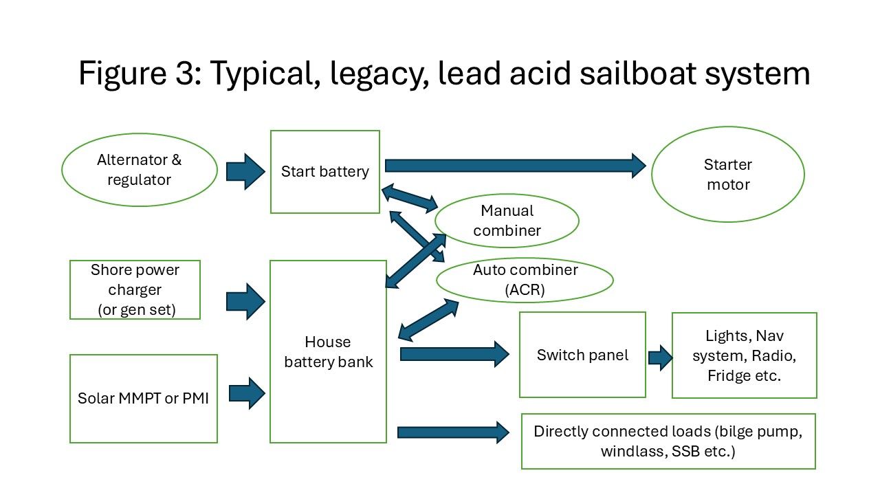
Figure 3 is a high level, very simplified, wiring diagram of the electrical system you probably already have on your boat. The first thing to say about that is that the Automatic Combing Relay (ACR) now needs to be removed. It was designed to connect and disconnect two lead acid battery banks under certain pre-conditions. At the voltage level that LiFePO4 operates at, the connection would be closed much of the time, thereby effectively wiring the two banks in parallel which, as we have discussed, is something we need to avoid. So, the first step is to remove the ACR.
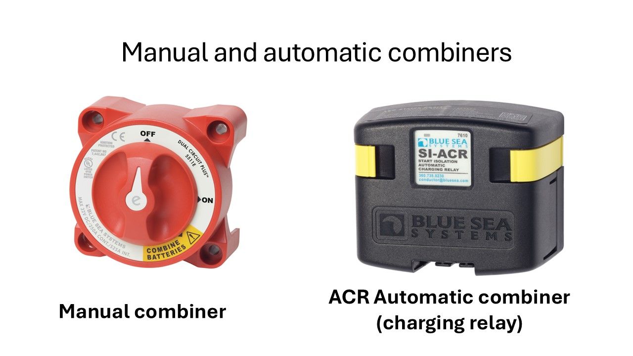
Retain the Manual Combiner
I am an advocate of retaining the manual combiner, first for its functionality as a high-capacity isolation switch but also for manual combining of the two systems in an emergency. As we discussed in “Lithium Batteries for Small Boats” there can be circumstances where a BMS will shut down the battery, including its system critical loads. The benefit of retaining the manual combiner is that it provides an immediate solution, by powering critical loads from the lead acid start battery.
Yes, we said earlier that you don’t want the two systems to be run in parallel but if your BMS has shut down the LiFePO4 house bank is, by definition, not in parallel. Moreover, even if it were, serving critical loads in an emergency, for an hour or so, becomes the more important consideration.
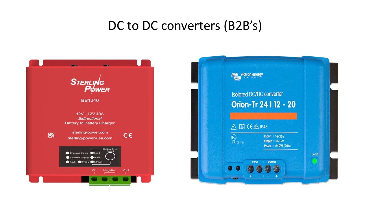
So, what are DC to DC Converters?
As is well known, since the time of Edison, we have had transformers that change the voltage level of AC circuits. Changing the voltage level of DC circuits only became viable with the development of solid-state power devices. Today, they can be found everywhere. They work by storing electrical energy momentarily (in either magnetic or capacitive charge form), before releasing that energy at a different voltage.
Some cruisers told me that DC to DC converters are overpriced, soak up energy and generate heat. As to the cost, it is peanuts compared to the expense of shortening the life expectancy of an expensive battery by years or, worse, creating a fire hazard. As to efficiency, it varies from manufacturer to manufacturer. Their efficiency is highest when converting similar voltages (say 11.6 V to 13.0 V) and less when converting dissimilar voltages (such as, say, 12 V to 48 V), but you can read the manufacturers specifications to determine this.
One simple indication of the efficiency of a unit is the size of its heatsink (if it is excessively large it implies that it generates heat). The one I purchased operates in the 95 to 98 percent range and I have not felt any significant heat arising from it.
Uni-directional or Bi-directional
A key thing to consider when buying a DC-to-DC converter is whether it is uni-directional or bi-directional. I purchased a bi-directional unit, because that solves many of the issues we talked about in the first article and simplifies the overall system.
Remember that the lead acid start battery will self-discharge when not in use (everyone seems to disagree on the precise figure but let us assume 5 percent per month, in the best case, when new). On a winter layup, for instance, which might mean 30 percent discharge or more, that may not be enough to get your engine started again in the spring. With your prior lead acid system, you would have had an ACR installed, ensuring that both banks remained topped up.
With a uni-directional DC to DC Converter, you lose that capability. Some cruisers have addressed such limitations with various configurations, including a second solar bank. A bi-directional DC to DC converter overcomes all of these issues. In the case of the unit I purchased, it is capable of delivering 40 amps in the primary direction (start bank to house bank) and 20 amps in the opposite direction, which is more than sufficient to keep the start battery charged in all foreseeable conditions.
New Wiring Configuration
With this approach, the new configuration is a relatively simple modification to the older system i.e.
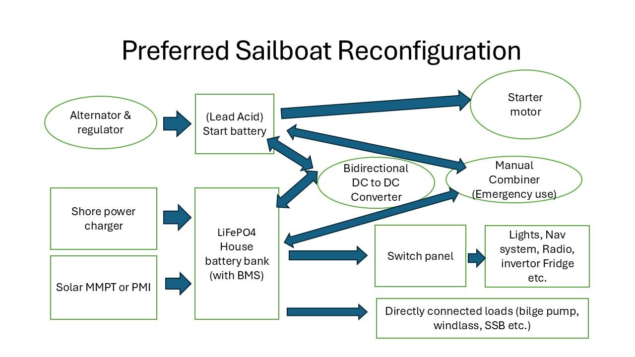
This approach:
- Allows critical loads to be serviced in the event of BMS shutdown;
- Gives you the best of both worlds. Safe, high cranking amps for engine starting and efficient LiFePO4 energy storage for all other loads;
- It avoids all the various concerns arising from connecting an alternator to a LiFePO4 battery;
- It is a solution where all the equipment is used within its intended design parameters, facilitating maximum life expectancy and eliminating the risk of denied warranty claims.
How to Service a Large Occasional Load
There are two other configuration issues, however, that we should address. The first relates to how best to service a large occasional load, such as an anchor windlass. The practice with an all lead acid system was to only operate such devices, while running the engine (so that the alternator provided voltage support). A second consensus was that you could wire these devices either to the start bank or to the house bank (as the ACR was likely closed, it may not have made any difference).
With a DC-to-DC converter in the heart of your new boats electrical system, however, voltage support from the alternator to the windlass (if wired to the house bank) is limited by the capacity of the DC-to-DC converter. That means, of course, that as you size your house bank you need to be aware that you will have this large load draining the battery, with limited alternator support. That is not a problem, provided that everything is appropriately sized.
The wholly acceptable, alternative approach would be to configure the windlass as a load served by the start battery. There is no absolute right or wrong way to approach this, and the decision largely depends upon the relative sizes of your windlass and battery systems. For my own installation, I wired my windlass to the house bank, primarily as I like the idea of all loads being captured by the new battery monitor.
Alternators and Alternator Sizing
Another issue to discuss is alternators and alternator sizing. I should first state a personal prejudice: I have seen so many alternator failures, in recent years, that I have now come to think of them as a consumable item. Consequently, I would be reluctant to spend a lot of money on an upgraded alternator. LiFePO4 batteries, however, do have this exceptional capacity for high rates of charge, so what are we to make of it? Online discussions frequently focus on upgrading alternator output but it’s appropriate that we consider a few constraints.
Mechanical Load
Firstly, remember that an alternator load is a mechanical load on the engine. A 100 A alternator would be a demanding about 1,300 watts (ignoring losses for a second) which is about 1.7 hp. That may not be a significant demand if you have an 80 hp engine, but it is significant for a smaller engine. Secondly, if you have the standard, single ½-in. V belt, you have to consider whether it is capable of delivering increased power. Gates belt sizing calculations guide that the biggest variable is the diameter of the pulley, with something like max 2.2 hp for a 3-in. pulley and 1 hp with a 2-in. pulley (at 1,750 RPM).
Shape
Next to consider is the physical mounting and shape of any substitute alternator. I once went through the entire stock of an automotive specialist’s alternator inventory, trying to find one that I could possibly use to replace my failed standard alternator (I was in a foreign port and couldn’t import the correct model). Eventually, with much cutting and welding, I was able to get one fitted and aligned but it was a lot of work.
If you are considering buying a high output alternator, therefore, make sure it is a suitable replacement and consider whether you need to upgrade to multiple V belts or a serpentine belt. Finally, most of us, when we run our engines, do so for multiple hours (primarily because there is no wind), which would be sufficient for most alternators and battery banks to put in a good charge. So, in reality, is there really an advantage in reaching full charge in two hours, rather than (say) three?
ABYC E-13 Standard
Finally, let us consider the new ABYC E-13 Standard, which will be a prerequisite, in future, for any marine survey and therefore potentially obtaining marine insurance. The simple answer is that AYBC is feeling its own way with the new technology, not wanting to frustrate innovation but, conversely, wanting to prevent obvious bad practice. Somewhat unfortunately, AYBC’s new standard apples to all lithium-ion types and is not specific to LiFePO4.
Publicly Available Requirements
Also, unfortunately, these standards are directed at equipment manufacturers, boat builders and professional electrical installation contractors and are expensive to buy, for an individual. However, they have made public the key features of their requirements and they are logical and similar to what we have suggested i.e.:
- BMS. They emphasize the importance of a robust Battery Management System (BMS) and allow this to be either internal or a matched external system. They establish guidelines for thermal management, to ensure that batteries operate within safe temperature limits. No electrical connections to be made in a way that could potentially bypass the BMS. When approaching a shutdown condition, the BMS is required to notify the operator with a visual and/or audible alarm.
- Alternative Power. The need for alternative power for critical systems, in the event of a BMS battery shut down.
- Lead-acid for Engine Starting. They suggest that installations (may) require a separate traditional lead-acid battery for engine starting. They also refer to the fact that many outboard engine manufacturers will not honor their warranties if their engines are connected to lithium-ion batteries (and the needs of high compression diesels are even greater).
- Requirements for Charging Systems. They outline requirements for charging systems, to ensure compatibility with lithium batteries, such as appropriate voltage levels, charging algorithms, and temperature compensation.
- Main Battery Switch. They require a main battery switch with the appropriate current rating to act as an isolation switch.
- Fuse and Circuit Protection. Proper fusing and circuit protection devices are mandated, to safeguard the entire electrical system, which includes a Class T fuse, as discussed in “Lithium Batteries for Small Boats”.
- Battery Installation. They specify how batteries are to be installed to prevent movement and provide ventilation while remaining watertight.
So, it is somewhat reassuring to know that the regulatory authorities have adopted near identical recommendations to the ones I support.


A few (more) comments:
1) Charging LiFePo4 directly from an alternator is not, in and of itself, a faulty solution provided that you have a modern regulator programmed correctly, you take reasonable precautions to ensure a BMS load dump doesn’t fry your alternator diodes (Balmar and Sterling both make alternator protection devices), and you have a means of keeping the start battery topped off (even a low output DC-DC charger works fine for most installations). I understand that you’re trying to educate the newbie here and that charging the lead acid battery directly is the safest way to go (especially for internally regulated alternators), but people shouldn’t write off the benefits of direct LFP charging. The thrifty among us might easily buy an older Balmar external regulator now that people are upgrading to the Wakespeed and Zeus, and thus have adequate control over alternator output. I would also mention here that if you are charging the start battery directly, alternator output will decrease precipitously at around 80% charge. That means not only is your start battery taking longer to charge, so is your lithium bank. I don’t know how this works in practice. Maybe the DC-DC converter will pump enough amps into the lithiums to keep the charge rate higher.
2) Many marine electrical experts have eschewed the use of a 1/2/B switch for LiFePo4 installs. I think I read somewhere that momentary combining of chemistries may be OK according to recent ABYC (someone check me on that) but to me that means combine to get your engine started. Now you need to ask yourself if your LiFePo4 battery bank can handle that amperage load. More dual purpose LiFePo4 batteries now available on the market.
3) I would provide LiFePo4 isolation with a 1/2/O switch after the Class T for safety. I think that this is an ABYC requirement too. Not sure a 1/2/B switch is really the proper LFP isolation.
4) As for alternator sizing and load management, this is another good reason to have an external regulator that you can program to account for belt sizing (essentially, derating the alternator’s output based on field voltage input), and for alternator temperature to avoid overheating.
I think that if someone wants LFP which is super simple and least expensive, your strategy is a good way to go but people should understand the limitations and the risks.
Good points:
1) I’ve observed just what your saying, as the B2B charger demands more power the engine battery voltage drops. My Victron Orion XS B2B charger will step up the output voltage to the program voltage/current until the input voltage approaches a setpoint minimum at which point it tapers the output current until the setpoint is maintained. So if the alternator can maintain the power requirements and the B2B charger is within limits the LFP bank will continue to charge at the programmed rate. I only see about a 0.5V drop at the engine battery while the Orions are changing at a steady 60A at cruising rpm. I’ve programed the voltage regulator to offset for this. At idle one of the Orions drops out due to low voltage and to protect the alternator. It delivers 30A and maybe a 0.8V drop at the engine battery.
Totally confused!
Sorry to see PS has morphed into crappy YouTube videos and advice from persons who blah blah too much. Just another bought by publication. So sad!
Great article. The only bi-direction DC to DC charger I’ve heard of is by Sterling Power? Its availability in Canada is more limited than some of the other brands. I noticed you did not specify any brands in your article? The technology is changing fast though so perhaps we’ll see others. It would be nice to see a multi channel charger that will charge lead acid and LiFePo simultaneously.
Hopefully, PS will string your articles together somehow so that when I read them again I don’t have to search for part 2, 3, etc.
Stephen Rietzel’s remark about stringing the articles of this series together is one I want to see also, as I’m about to refit a new boat and will be going with LiFePo4. This series is quite timely for my purposes.
I would love to see brand name suggestions, while recognizing that new gear for a new-ish technology of this sort comes on to the market with some frequency. When I wrote for SAIL, l would often mention a brand name I used, knowing full well that my editors would add in the names of other manufacturers (often advertisers of course!), giving readers options they could research and choose from if my solution didn’t work for them.
I would also – and this just might be my lack of knowledge of circuitry – like to see the above battery configuration diagram presented as a proper circuit diagram so that I can comfortably use it as a template for my installation.
Thank you for the articles. They are very informative and helpful. One thing I would like to see is adding in firefighting equipment. A typical boat, in my understanding, does not have the firefighting equipment on board for Lithium batteries. ABYC E-13 is somewhat vague about this saying only that you need to follow the battery manufacturer’s recommendation for firefighting equipment. NOTE: I have not researched what NFPA has to say. I have heard talk of and seen an install on a sailboat where the Lithium battery bank was installed in a dedicated box with a seacock attached so it could be flooded in the event of fire (I don’t know which specific Lithium chemistry batteries are installed). That worries me, especially in a salt water environment.
Thank you for these articles. I converted my boat in early 2024 and concluded the same after considerable research. However, I excluded the 0/A+B switch as it didn’t seem to provide much benefit for the risk. Instead I used two B2B chargers which together provide up to 100A and some backup redundancy. I can reverse one or both if the engine battery need charging. The two chargers are set to taper off at different engine battery voltages so as the rpm drops the chargers decrease their demand protecting the alternator (one set for idle and the other for cruising rpm). A Balmar alternator voltage regulator also tapers the alternator field voltage if the alternator overheats providing redundant protection. This system provides excellent trim control to get the most out of the alternator without damaging it.
The reason for keeping a manual emergency combiner is, in the event of the BMS shutting down the LiFePO4 house bank, you have the means to energize critical loads (such as navigation or VHF) from the lead acid start battery, possibly under time critical constraints. That is a reduction, not an increase in risk.
As for doing the opposite (using the house bank to support a flat, lead acid start battery), that is not something I would ordinarily recommend, but a lot would depend on the specifics of your battery system. As you say, much better to ensure the start battery always gets a good charge.
I wonder about your criticism of the BankManager.
Have you actually used one or tested one?
I see many people reporting good results with it and the inventor is a very experienced electrical engineer.
I’m thinking of buying one but now I’m having 2nd thoughts.
I came across the ‘Bank Manager’ just over a year ago and got into a discussion with the proprietor at the time, as to how it functioned. Once we got past the (shallow) marketing claims, it emerged that it is simply a programmable switch, that connects the lead acid and LiFePO4 batteries in parallel, under certain preset conditions. That means you are operating your LiFePO4 outside the manufacturers intended parameters, almost certainly shortening battery life and invalidating any warranties. I wouid also be concerned that you are increasing the risk of thermal runaway, although that would need more study. Moreover, while the proprietor criticizes DC to DC converters as unnecessary, power hungry and overpriced, the price for his simple switch is comparable, which makes no sense at all. I dont know what the qualifications of the proprieter are (i thought maybe more an instrument engineer than an electrical engineer) but that is not really relevant-techology is moving so fast that anything he might have learnt at school on this subject will be obsolete. Conversely, I worked closeiy with battery and equipment manufacturers, to give the most valid and current information, which is as summarized in this series of articles. Good luck with your installation.
The Bank Manager that is available controls charging via measuring current not voltage. This is much better for LiFeP04. It is not a simple switch. The inventor is an experienced and accomplished electrical engineer.
From what I’ve read here he is far more familiar with BMS requirements and LiFeP04 charging parameters than Mr Burnage.
The total market for LFP related devices is far bigger than just sailboats – it also includes commercial vehicles and vessels, RV’s etc, globally. A $billion + market. There are two possibilities, therefore: Either that proprietor is such a genius that he has figured out something that the dozens of long standing Chinese and Western companies, in the field, all with their own research teams, have failed to see – OR, they see it for what it is. You decide which of the two you believe in.