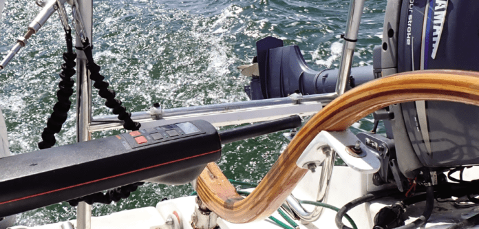
Self-contained tillerpilots are a simple and darn handy means of steering a smaller sailboat, particularly when sailing solo. For the singlehander a tillerpilot is invaluable when you are hoisting and dousing sail, tacking in a breeze, or ducking below to grab a sandwich. When you’re cruising, the tillerpilot relieves the tyranny of the tiller, and probably steers a better course than you can, especially as your mind wanders.
Installation is dead simple. A pair of wires (a few more if you add wind instruments or a remote), a pin on the tiller, and a mounting socket on the coaming or seat. The makers even specify the exact installation dimensions; a one-size-fits-all design. Raymarine and Simrad dominate the tillerpilot market, making very similar units with nearly identical mounting arrangements. This article is based on the Raymarine ST2000. The test boat for this exercise is my Corsair F-24 MKI trimaran, 24 feet long and weighing about 2300 pounds as sailed.
When deciding where to mount the tillerpilot, two measurements are important. I’ll be referring to these two measurements throughout this report.
• Dimension A, measured athwartship with the tiller centered, is the distance between the mounting socket for the drive unit and the pin on the tiller where the drive arm connects (socket to tiller-pin).
• Dimension B, measured fore and aft, is the distance from the head of the rudder stock to the pin where the tillerpilot connects (see Figure 4 in “A Modified Tillerpilot Setup”).
The reason for Dimension A is obvious. The tiller needs to be centered when the drive is centered (24.5 inches for Raymarine tillerpilots, 23.5 inches for Simrad tillerpilots). Extensions are available to move the mounting socket or extend the pushrod to accommodate wide cockpits, high coamings, etc. (The requirement for the drive to be level is also obvious; an upwards angle will allow the push-rod to lift off the pin.)
The reasoning behind Dimension B is less obvious. The length of this measurement will determine the amount of leverage the pilot can exert, the range of tiller motion, and the velocity at which the push-rod moves the tiller. Doesn’t the required tiller movement and speed vary from boat to boat?
Theoretically, a 36-foot boat would requires 50 percent greater movement (in degrees) to create the same rate of turn as a 24-foot boat, since the rudder is 50 percent farther from the keel, but the heavier boat carries more momentum through tacks and probably favors a slower turn. The same is true of adjustments for gusts and waves.
How far and how quickly we move the tiller also depends on boat speed (a faster moving boat will require less rudder to change course), waves (rough seas require more exaggerated rudder movements), and crew. There is no point in tacking faster than the crew can get the jib across.
I know that if I casually tack a multi-hull in rough conditions, I can risk getting stuck in irons. Also, I move the tiller farther and more quickly in a dinghy than on a cruising boat. Based on these observations, it seems like Dimension B should be shorter for boats that require greater rudder movement to respond. Raymarine calls for a distance of 18 inches, but I’ve seen numerous installations as short as 14 inches on smaller boats, and the owners seem pleased.
TAKING A TEST DRIVE
Before making changes to the mounting position, go sailing and carefully observe the following on your boat:
• Range of Motion When Tacking. What is the average range required to tack? The tillerpilot applies its maximum range when you engage “autotack,” so you want that range to be close to what is required for your average turn. A smaller angle may put you into irons. An angle slightly larger than needed may help give you more time for you to tack the jib.
• Required Drive Force. How hard do you need to pull on the tiller during a hard gust? How hard do you pull at the extreme range when tacking? To estimate load on a tillerpilot drive, multiply the maximum force you apply by the length of the tiller in inches, then multiply that by 150 percent to allow for waves. Divide that number by 18 inches (Dimension B, the suggested tiller-pin location). Then apply a generous safety factor for long life. For an example, see the table “Corsair F-24 Helm Data”.
• Rate of Speed. How fast do you move the tiller? Observe your helm over time both tacking and sailing off the wind. These are typically the quickest helm movements that a tillerpilot will be expected to carry out.
Faster isn’t always better. For example, you shouldn’t just slam the rudder over to leeward when tacking; that stalls the rudder, increases turbulence over the hull, and slows the boat. Instead, move the tiller gradually but steadily until the maximum rate of turn is achieved.
We want to do the same thing when exiting a turn. You want to move through the turn quickly, but without slowing too much. The optimum rate of turn varies with speed, wave conditions, and hull design. (Note: If the push-rod rate is too slow, its adjustments could coincide with the boat’s yaw, initiating cyclical yawing, which will be noticeable as the tillerpilot over-compensates).
As you determine this criteria for your boat, you effectively create a rectangular zone within which you can install your tillerpilot. Raymarine used to allow this kind of flexibility in their installation manual, stating that measurement B could be anywhere between 14 to 18 inches. For its newer EV series, the company has settled on 18 inches.
I measured the dimensions my dealer had used to install my Raymarine ST2000 tillerpilot on our Corsair. Dimension A was as prescribed—24.5 inches from socket to pin. To my surprise, Dimension B was 21 inches, considerably greater than the manufacturer’s recommendation. This was probably why the autotack feature did not work well on my boat, especially at low speeds, or in a seaway. The installer had simply picked the most convenient place to mount the socket.
To find a more effective location for the tillerpilot, I measured my maximum and typical rudder angles when tacking in a range of conditions (see “Corsair F-24 Helm Data”). In very light winds or big waves, I apply more helm, as much as 25 degrees (50 degrees total). In average conditions I apply about 20 degrees (40 degrees total). I may occasionally use more than 25 degrees when docking, but I don’t need that range on autopilot.
The tillerpilot hard-over time is actually a little quicker than my typical tacking turn, but since the dealer-installed tillerpilot’s maximum rudder angle (26 degrees) is less than what I’ve found to be optimum (40 degrees), the faster helm helps offset this deficiency.
HELM FORCE
Assuming reasonable sail balance, the highest tiller force measured at the end of my tiller is about 10 pounds. This is equal to about 16 pounds of force at a point 18 inches from the rudder stock and equal to 21 pounds force at 14 inches. The tiller load during ordinary sailing is less than 2 pounds (see “Corsair F-24 Helm Data”).
TYPICAL SPECIFICATIONS
The stroke length for both the Raymarine ST1000 and ST2000 is 9.3 inches. For the Simrad TP10, TP22, and TP32, the stroke length is 10 inches.
This means that the standard installation allows for about 16 degrees in rudder angle change (32 degrees total), or half of the usable rudder range, depending on the boat. The maximum force for these tillerpilots ranges from 125-170 pounds, the equivalent of 70-90 pounds of force at the tiller end.
To keep forces well below this maximum, I aimed to keep tillerpilot loads in any installation below the equivalent of 24 pounds when steered by hand. This is a very heavy helm, but some of the tillerpilot setups we tested were very inefficient, and the tiller required more force than normal.
The Raymarine ST2000 takes 4.5 seconds lock-to-lock (push-rod fully extended to fully retracted). The Simrad TP32 needs 4.7 seconds. (Lighter duty versions are about half these speeds.) This is fast enough for boats of average weight and greater than 25 feet, but a little slow for multihulls and sport boats.
The test boat for this exercise is a Corsair F-24 MKI trimaran, 24 feet long and weighing about 2,300 pounds as sailed. The rudder stock is located about 10 inches forward of the transom and the centerboard is about 3.5 feet deep. The tiller is 31 inches long.
When sailing to windward, the helm is very light, and because the rudder is small and well balanced, the helm remains light even during sharp maneuvering. One finger is all you need most of the time, even past the reefing point.
INTERNAL COMPASS
In some non-standard installations, the unit will not be at a right angles to the centerline, causing the compass deviation to change through the tack. This has the effect of reducing the autotack turn angle during the latter portion of the tacks to port, slowing the completion of the maneuver. The compass deviation during our testing ranged from 4 to 13 degrees, and depended on the angle of the tillerpilot during a turn.
This temporary deviation is relatively harmless, and disappears when the tiller re-centers on the new tack. In a standard installation, when the tillerpilot is mounted square to the tiller, this type of error is non-existent.
On a related topic, before installing a tillerpilot, use a hand-bearing compass to check for deviation at any potential mounting locations. Be careful where you place large metal objects (or devices with magnets). A chisel next to a tillerpilot is enough to fool its internal compass.
IDEAL TILLER-SOCKET DISTANCE
In the Corsair, we found that 14 inches for Measurement B offered the best compromise. But every boat is different.
If you have a full keel boat with a barn-door rudder, the helm can get heavy in strong conditions, so you want to increase the tillerpilot’s leverage. You can do this by adding another tiller-pin closer to the tip of the tiller.
If you place the tiller-pin at 22 inches (instead of the prescribed 18 inches), your leverage is increased by 21-22 percent. However, the helm range is reduced by 18 percent.
The 18-percent reduction in helm response is unlikely to make a difference when sailing a straight line and you could increase the unit’s gain setting by one level to compensate. If you want greater rudder angles, leave the original, 18-inch tiller-pin in place.
This you will give you a setting for normal sailing loads (18-inch position) and another for heavy-weather (22-inch position). In the higher leverage, “heavy weather” position, you’ll need a short push-rod extension to center the tillerpilot, but this isn’t essential if you are sailing a straight line and not using the tillerpilot to tack.
Or maybe you have a light boat that would benefit from quicker tacking in some conditions. If you can’t move the mounting socket farther aft, perhaps you can move the pin aft to 14-16 inches and extend the pushrod 0.6 to 0.8 inches using a DIY extender (see “Essential Autopilot Accessories”). Alternatively, you can extend the pushrod with a Raymarine Pushrod Extension ($32). The leverage is reduced, so don’t try this on a boat of more than 4,000 pounds or you can strain the tillerpilot.
SEA STATE ADJUSTMENTS
All installations can benefit from a review of the standard gain and damping settings. Gain determines the amount the drive reacts to being off-course. Damping (sea state) determines the delay before the tillerpilot makes a correction.
Use too much gain and the boat will overshoot, steering to both sides of the true course. Use too little gain and the boat will never quite reach the new heading. Too little damping and the pilot will be adjusting constantly, eating amps and wearing itself out, but with too much damping it will wander far off course before the rudder corrects.
Can we compensate for incorrect pin location with tuning alone? Only within limits, because gain and damping don’t change the speed of the drive or the length of the stroke. These settings are for dealing with sea conditions, not the geometry of the installation.
However, if you shorten the distance between the rudder stock and tiller pin (Dimension B) you may need to reduce gain to avoid overcorrection. Similarly, if you lengthen the same dimension, you may want to increase gain slightly to correct for the reduced helm range. Review your manual for more information on tuning gain and other features.
TESTING INSTALLATIONS
Decades ago, I installed a Simrad TP22 on a Stiletto 27 catamaran (1,800 pounds fully loaded). I decided to set Dimension B at an excessive 43 inches because I could not install it farther back on the hulls.
It worked fine at high speeds—we motored and sailed at 12-16 knots much of the time—but it would not autotack and it could not control the boat when we were hoisting sails at slow speeds. I considered creating a quadrant to solve the Dimension B problem, but that seemed impractical.
So, I compensated. The cockpit was laid out so that tacking while single-handed was not difficult. When taking the sails down, I just motored faster to stay on course. I had hank-on sails, so this often resulted in a bouncy dance on the foredeck. The lesson here is that if you increase Dimension B to get more leverage, this ultimately limits the range of rudder angle.
The dealer installation of the tillerpilot on my F-24 was also incorrect. Although Dimension A was correct (24.5 inches), Dimension B was 21 inches, a full 3 inches beyond the factory recommendation of 18 inches. I selected the two most promising options from my drawings and tested them against the dealer positioning. For the following installations, I did not change the gain settings:
• 21-inch socket, 21-inch tiller-pin. At normal sailing and motoring speeds, steering was stable with this arrangement, but sluggish when changing course. At slower speeds, such as hoisting sail into the wind, steering was erratic and off-course alarms were common unless I maintained a minimum speed of 4 knots. The autotack feature did not function, and frequently put the boat in irons. I could make autotack function in most conditions if I first pushed twice on the +10- degree course change button, but the turn was still slow and the boat would come out of the tack 20-30 degrees broad on the wind.
• 14-inch socket, 14 inch tiller-pin. The autotack turns to port were considerably crisper. There was less compass deviation than in a setup that relocated only the tiller-pin to 14 inches. With the tillerpilot square to the centerline, the compass read true. With the tillerpilot in this position, I tacked singlehanded 15 times in a row.
It came out of the tack on-course and with good speed every time, because the turn was consistent and because I could trim sails without distraction. I tested this setup in winds from light to 20 knots; beating, power reaching, and broad reaching; tacking, jibing, and hoisting sails. Yawing while broad reaching was very noticeably reduced.
The only problem I noticed was that the gain was a bit too high going dead downwind in light air. The solution was to move the pilot to the original 21-inch pin and socket positions, which is simpler than adjusting the gain setting and has the same effect.
• 21-inch socket, 14-inch pin. By adding a 0.8-inch pushrod extension to center the tiller, steering was improved. Autotack worked, and steering at lower speeds was also greatly improved. I sailed for hours with this combination.
A DIY TEST
Want to try different tillerpilot positions without drilling holes? Mount a tiller-pin on a metal plate and strap that to the tiller with hose clamps (padded with cloth or tape). Extend the push-rod as needed with the rubber hose DIY extension. This will let you know if it will be worth the effort to also move the tillerpilot mounting socket to a new location.
CONCLUSION
We understand why the manufactures are firm in their one-size-fits-all installation recommendations. For most boats the results in helm angle and pushrod force are in a reasonable range that will not damage the tillerpilot. Even small installation errors, unless well thought out can result in poor performance and potentially damage to the unit by overloading it. But smart adjustments may help boats at both ends of the size spectrum.
The maximum tillerpilot helm range should coincide with the average helm used when tacking. Less range means you might not make it through the tack, and too much movement will make the boat turn too fast for the jib to come across.
For heavier boats we recommend adding heavy weather pin at 20-22 inches; you will lose some loss in tacking ability but the pilot won’t work as hard. For quick boats, reducing Dimension B to 14-16 inches can improve tacking, performance at low speed, and performance in waves. And by all means, keep the standard locations. They may be best for routine sailing. Another option is to upgrade to a Pelagic Standard Tillerpilot, which we will discuss in an upcoming review.
Tiller-steered boats should be designed with tillerpilot mounting in mind. If a dealer installs your tillerpilot, ask them to use the prescribed mounting positions. After careful evaluation and testing at sea, there is room for modification.


