


For almost any vessel over 20 feet there are three groups of marine electronics that are valuable to have on board, not only for efficient navigation, but also for safety. Collectively, these systems not only serve to protect your investment, but might also save your life. They are, respectively, devices for communication, location, and collision avoidance.
In the first product group, the top item is a VHF radio. Every vessel should have a fixed-mount, 25-watt VHF, as well as a handheld VHF as a backup. In the second group—location devices—the top gadget is a GPS. All sailboats of this ilk should have a fixed-mount GPS unit, and a handheld GPS as a backup. And in the final essential product group (collision avoidance), the best way to avoid running into an object or avoid being hit by another vessel is to have a radar reflector and a marine radar system.
Marine radars, like GPS units, have improved in quality, power consumption, and price in recent years. Gone are the days of the “stick your face in” radar. Those systems were initially replaced with brighter monochrome CRT (Cathode Ray Tube) radar systems that consumed power greedily. And these days, CRT radars are being replaced by LCD (Liquid Crystal Display) display systems.
A Little Background
Radar is an acronym for “RAdio Detection And Ranging.” A radar system operates in the microwave part of the radio-frequency spectrum used to detect the position and/or movement of objects.
In 1887, Heinrich Hertz, a physicist, began experimenting with radio waves in Germany. He found that radio waves could be transmitted through different materials. Some materials reflected these radio waves. He developed a system to measure the speed of the waves. The data he collected and his experiments generated much interest and led to further development. Hertz’s experiments were the first steps in the development of radio communication, and later radar.
Radar works in a similar fashion to your voice echoing in a large open room or in a valley or canyon. Essentially your voice is the transmitter. When the energy from your vocal cords hits an object, some of it is reflected back. That reflected energy is perceived by your ears. The longer the sound takes to return, the farther away the object is from you. Also, the louder the return echo, the bigger the object that the energy hit.
With most radar systems, position is determined in two dimensions: compass bearing and distance. The display presents position information in polar coordinates commonly referred to as PPI or Plan Position Indicator. A rotating antenna transmits pulses at specific intervals known as a duty cycle. The time delay between a transmitted pulse and the echo, or return pulse, determines the distance of the target for each azimuth direction on the display. The greater the echo delay from a particular object, the farther from the display center that object appears.
When you are choosing a radar system for your boat, there are a couple of specifics you should keep in mind. While transmitting range and power are important, they are not the only factors that should influence your decision. The range of a radar system depends on several variables, and the height of the scanner above the waterline is chief among them. Radar range is directly related to height—the higher up the radar is, the farther it will see. Mounting your scanner well up in the rig can be a great asset. Keep in mind, however, that by doing so you’re creating a greater circle around the vessel that the cone-shaped energy beam issued from the scanner will not see. Thus any targets in this circle will not return echoes. Of course these are close-in targets and they’re the ones that are most important for you to be aware of. Who cares if you can see a passenger ferry 48 miles away? You want to see that powerboat screaming towards you in the fog on your two-miles-or-less scale.
Typically, sailboat installations have the radome—the unit that houses the rotating antenna—mounted near the first set of spreaders or around 20 feet above the waterline. In powerboats, the radar is either mounted on a radar arch or on a deck above the pilothouse. If you mount the antenna higher than 22 feet above the waterline, you will not gain much in range, but you may lose more close-in targets. Another critical consideration regards the installation of the scanner. It should be put it in a location where the beam that it issues will not pass through GPS sensors, Loran or weather fax couplers, and most importantly, people. Keep the antenna at a minimum of two feet above and least five feet from where you, your crew, and your passengers spend the majority of your time on board.
When you are looking at the power output of radar systems, in most cases a 2kW radar system can give excellent target imaging for inshore applications on 20- to 50-foot vessels. Higher power ratings like 4kW and 6kW systems may have a longer “range” than a 2kW system, however, the real performance gain is seen when the weather conditions are bad.
Rain and snow have a tendency to reflect and absorb radar energy. When the energy is reflected we are able to see the size and the pattern of the storm. Because rain and snow absorb radar energy, they can block your view of targets and land masses. This is where additional power becomes an advantage. The increased energy punches through the weather and allows you to see the targets. Fishing vessels, for example, like to use higher power radars to see indicators like birds working an area of bait.
The LCD revolution has helped with the lower power consumption. The CRT displays wasted a lot of power just in heat dissipation alone. Older styles of radar generate high voltage to keep the magnetron “heated” and ready to operate in the displays. Via the scanner cable, they supply the voltage, and more importantly the current, to the scanner assembly. More current is required to carry the voltage to the scanner. Modern marine radar systems generate the high voltage required for heating the magnetron in the scanner assembly, but there is no power loss as the high voltage is generated and consumed in the same location.
Power consumption of current marine radar systems is surprisingly low, when you consider small vessel radars range from 2kW to 60kW. This is the case for two reasons. This power rating is a peak power rating, and that amount of energy is being used for an extremely short time, typically less than a millionth of a second. This pulse will repeat many thousands of times per second. Most small vessel radar systems usually consume less than 75W of power when operating.
The size of the radar antenna is another important variable to look at when choosing your radar system. The antenna transmits the energy at a “wide” vertical angle to cover the entire target range area with radio waves. The antenna also transmits at a “narrow” horizontal angle. This allows the system to see targets that are close together, so that the targets are perceived as individual items as opposed to one large mass. This discrimination of targets is called resolution. A vertical beam angle of about 25 degrees is common to most systems. The length of the antenna determines the horizontal beam width. The longer the antenna, the more narrow the beam’s horizontal width, creating greater target discrimination or resolution. Short length antennas (18″ and 24″) typically housed in domes provide approximately 6 to 3 degrees of horizontal angle. Open-array antennas, typically 2′ to 12′, produce a horizontal beam from 3 to 1.9 degrees.
Test Parameters
We wanted to look at marine radar systems that a majority of boaters could afford and install in about a weekend. So, we evaluated entry-level, stand-alone radar systems. The products that interested us most were 2kW radar systems with monochrome and color displays. We chose those with list prices under $2,000 for the monochrome systems and under $3,000 for the color systems.
Among the monochrome systems we selected are the Furuno 1623, the Furuno 1712, the JRC RADAR1000 MKII, JRC RADAR 1500 MKII, and the Raymarine SL72 Plus. We tested two color systems: the JRC RADAR 1800CP, and the Simrad RA30.
We conducted our tests along the shores of Long Island Sound at Avery Point, close to the University of Connecticut Avery Point Campus. We chose this location for several reasons: It allowed the tests to approximate actual use on a sailboat because all the scanner domes were affixed at approximately 15 feet above sea level. Also, this site sits in close proximity to two sets of fixed radar targets. The first is the New London Ledge Light House, and the second was a set of rocks closer to the water—Black Rock. This is also a high-traffic area for automobile and passenger ferries and other large vessels moving in and out of New London Harbor, giving our units lots of targets in motion.
We evaluated the systems with the following concepts in mind: product construction, installation and set up adjustments, menu navigation, functional control, and target resolution. All of the systems evaluated have NMEA 0183 inputs. This is a valuable feature to have in your radar because you can interface the unit with your position finder and view your own vessel’s position on the radar screen. And this interface will give you range and bearing to a waypoint, if you have one selected. If you have NMEA-capable instruments on board, you can also display that information on your radar display.
Display and Construction
The most evident improvements in marine radar have come in the displays. All of the radar systems we evaluated had waterproof displays, which is the biggest improvement of LCD systems vs. CRT systems. Now you can mount these newer displays in exposed areas, like on a cockpit steering pedestal. The systems we evaluated also allowed for mounting in a dashboard or hanging down from the overhead of a pilothouse. Two of the systems—the JRC RADAR1800CP and the Simrad RA30—are color LCD display systems with 256 colors and high resolution. These offer much greater detail and target discrimination than is possible with 8, 12, or 16 shades of gray. We also found the viewing angles of the color LCD displays much improved.
Radome technology is another area where critical improvements have been made. Radomes are now lighter and more powerful, with tremendous capabilities in a small package. The radomes we examined weigh from 8 to just over 14 pounds, and all of them make very little noise when they are working. This enhanced quiet while transmitting is due to better electronics driving the pulse circuitry. And all the units we tested had good seals where the fiberglass dome meets the base. Additionally, all these radomes have drip holes to drain off condensation. (An important aside about installations: Do not block or caulk the drip holes in a radome. Your efforts to stop moisture getting into your dome will likely backfire. Blocking the drip holes will cause condensation and salt to build up in the radome and probably lead to a system malfunction.)
Installation and Set Up
After installing your radar system, three parameters need to be addressed for the system to be considered operational and reliable. For our test, we carefully followed the system manuals to properly complete each adjustment and evaluate the navigation of the menus.
Tuning control: All of the systems we looked at had automatic tuning control. Control of the receiver circuitry by this system processor has taken a lot of the guesswork out of setting this parameter. You no longer need to adjust the tune after the antenna electronics warm up or cool down. We wanted to test how well the Auto Tune function worked with the products so we manually adjusted the tune controls and found that the factory presets were almost always on the mark.
Bearing Alignment: This process is completed to ensure that targets appear at their correct bearing relative to the ship’s bow. As with the tune adjustment process, the factory presets were very close to what we ended up with after the manual adjustments were completed.
Display Timing Adjustment: The length of the cable used to connect the display unit to the scanner can affect the display timing, which in turn can have an effect on the short-range target accuracy. If you have extended or reduced your antenna cable, you will need to complete this adjustment. Incorrect timing is most noticeable on the 1/8- or 1/4-mile range scales. Long targets like bridges or breakwaters may appear to be curving away (timing is early) or pulling in (timing is late) from the vessel. When you complete your installation, check out the timing parameter to be sure you have the proper antenna timing. For our review, we completed a tune adjustment and bearing alignment on the systems. Because we did not modify the original scanner cable, there was no need to adjust the system timing.
Menu Navigation
Current marine electronics controls fall into two groups: dedicated function control buttons (direct entry) or multi-function control buttons (menu driven controls). Both styles of control have advantages and disadvantages. If a system has all direct, entry controls, there are more buttons on the display and it can be confusing. A system with menu driven controls has fewer buttons, but each button contains more controls and this can be just as confusing. We like a little of both, which allows the operator to easily control the display with the fewest button pushes.
Target Resolution
All of the displays we reviewed returned decent targets. We can happily report that none performed poorly. They all returned targets giving us our location in relation to the shoreline and the fixed targets of New London Harbor.
Additionally, all but one of the displays we tested had a resolution of 240 x 320 pixels; the Simrad RA30 had double that (480 x 640), so its target information showed up more brilliantly. All of these had varying levels of brightness and contrast, with adjustable backlighting. We evaluated the displays in bright sunlight and the target information on all of them was easily viewed.
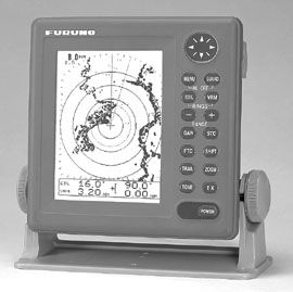
Furuno 1623 and 1712
The 1623 radar system offers a high-contrast, 6″, silver bright, LCD display and the 1712 system has a 7″, silver bright display. Both systems have four gray-tone levels to display target intensity. The 1623 system has 13 ranges 0.125 to 16 nm and the 1712 system has 14 range scales from 0.125 to 24 nm. Both systems offer a watchman mode, which intermittently takes the system out of standby and transmits for a number of sweeps to save power. This mode allows the 1623 and 1712 to only use about 8W of power.
The 1623 system has a 15″ dome weighing a little over 10 pounds. The antenna has a 25-degree vertical and 6.2-degree horizontal antenna beamwidth with 2.2kW of transmit power. This system has a feature that none of the other radars have. The rotation speed of the antenna is variable. The 1712 radar system has an 18″ radome weighing almost 11 pounds. The antenna has a 25-degree vertical and 5.2-degree horizontal beamwidth with 2.2 kW of transmit power, and rotates at 24 rpm. It is also wind load rated to 100 knots. Both systems come standard with a 10-meter antenna cable.
The best combination of menu navigation and system control goes to the Furuno 1712. This system had the most direct entry style menu control of the most vital functions What we liked the most about the Furuno 1712 was when you wanted to increase or decrease range gain, or use the EBL and VRM controls, they were easy to initiate and control. This is a great feature to have on a pitching deck or nav station. Even while navigating the various menus during the installation setups, this system was consistently easy to operate.
The Furuno 1623 system beat out its sibling for the best target resolution of all the systems we evaluated. The target returns were very consistent and strong, and there’s a good reason for the strong returns. As we mentioned, this system is the only one evaluated that has variable antenna rotation speed. The scanner rotates 24 rpm on the 3-16 nm scales, 31 rpm on the 1 to 3 nm scale and 41 rpm on the 1/8 to 3/4 scale. What does this mean? At the lower ranges, (the range that you should be using for collision avoidance), the antenna is transmitting energy and receiving echoes at a faster rate. This keeps the system receiving target information at a faster rate and displaying that target information with greater resolution or detail.
The NMEA interface cable for these systems is not standard like the other systems we evaluated. The interface cable for the 1623 has a $45 list price and the NMEA cable for the 1712 system is $35.
JRC 1000 MKII & 1500 MKII
Both the 1000 MKII and the 1500 MK II systems offer a 6″ monochrome display with a resolution of 320 x 240 pixels, 9 range scales 0.125 to 16 nm, joy stick control for menu functions, a jog dial to operate range sea clutter, gain and rain clutter, and a power-save transmission mode. The JRC 1000 MKII and 1500 MKII have plastic, four-way mounts making it easy to dismount the display on and off with the touch of a release button. This is a handy feature for those boat owners who want to stow their display below decks. All of the JRC models have rubberized covers over the scanner-display connector.
The 1000 MKII has a 12″ dome weighing less than 9 pounds, making it the lightest dome we evaluated. This unit has a 30-degree vertical and 7-degree horizontal beamwidth antenna with 1.5 kW of power. The transmit power of the 1000 MK II was the lowest of all the systems tested, and the antenna rotates at 32 rpm.
The 1500 MKII has an 18″ radome weighing about 11 pounds. It also has a 5.2-degree horizontal and 30-degree vertical beamwidth and a 2kW transmitting system. The rotation speed for the 1500 MK II is 32 rpm. In standard transmit mode, both the 1000 MKII and the 1500 MKII have the lowest power consumption of the systems evaluated. And both systems come standard with a 15-meter scanner cable.
In our test the JRC 1000 MKII and 1500 MKII had mostly a menu-driven control system. We found this a little awkward when completing the system adjustments. You need to pay close attention to the parameter you are adjusting such as range or gain and sea clutter. JRC models feature J-Dial and joystick controls to work you through the menus. This is where a couple of dedicated buttons would help.
As we mentioned previously, all of the systems we evaluated displayed our test targets and an outline of the shoreline well. With 1.5kW of power, we found the 1000 MK II target returns the weakest of the systems tested. There was more target fading than with the other systems and the consistency of the shoreline information detail that was displayed again was lacking in comparison to the other products tested. The 1500 MK II did offer better target displays than its sibling, but in this facet, the other systems evaluated performed better.
JRC 1800CP
The 1800CP from JRC has a 6.5″ color LCD, sunlight viewable, water-resistant display, with a display size of 320 x 234 pixels, 9 range scales 0.125 to 24 nm, joystick control for menu functions, a jog dial to operate range sea clutter, gain and rain clutter, and a power save transmission mode similar to the 1000 MKII and 1500 MKII systems. The 1800CP is also a C-Map NT+ chartplotter. Although this product was not evaluated for its plotting functions, that feature adds to its value as a collision-avoidance system.
The 1800CP has an 18″ radome with 32-rpm rotation speed. It weighs 11 pounds and has a 5.2-degree horizontal and a 30-degree vertical beamwidth, with 2kW of transmit power. This system comes standard with a 10-meter radar cable.
Like the other JRC models tested, the 1800CP has a menu-driven control system with other direct entry function keys for the chartplotting features. The system displayed good target information, and like the 1000 MK II and 1500 MK II, there is an NMEA interface built into the power cord.
The target display and resolution of the 1800CP was the best among the JRC systems we evaluated. The 2kW of power is complimented by high-quality, front-end receiver circuitry. This put it equal to the Simrad RA30 and just below the Raymarine SL72 Plus system for target resolution.
Raymarine SL72 Plus
The Raymarine SL72 Plus system has a 7″ monochrome display with four gray scales for target discrimination. The resolution of the display is 320 x 240 pixels, and there are eight levels of display backlighting with three levels of keypad backlighting. The system can operate on 10.7-44 VDC and only consume 10W of power with full back lighting turned on while in standby mode. There are two variable range markers and electronic bearing lines and there are 9-range scales from 0.125 to 24 nm.
The SL72 Plus system comes with a standard 15-meter radar cable and an 18″ radome. The antenna rotates at 32 rpm and has a 5.2-degree horizontal and 30-degree vertical beamwidth with 2 kW of transmit power.
The SL72 Plus was a close second for its combination of menu navigation and system control. The Raymarine manual was useful and easily comprehended. Dedicated hot keys at the bottom of the display can bring up commonly used functions, so adjusting through the system menus was smooth. The SL72 Plus also includes a handy laminated bridge card with a quick guide for navigating the system menus while underway.
The constant and full target returns gave this unit a Good rating in that part of our evaluation.
Simrad RA30
The RA30 radar system is the second color system that we evaluated. The RA30 has a 7″ color TFT display. The display has a resolution of 640 x 480 pixels, higher than the JRC 1800CP. Target information is presented on the display in four different intensity levels. This provides a crisp display of the information. The RA30 radome measures 18″ and has a horizontal beamwidth of 5.9 degrees and vertical beamwidth of 25 degrees. The antenna rotates at 24 rpm and has 2kW of transmit power. The radome comes with a standard 15-meter antenna cable. Like the JRC system, the RA30 unit had rubberized covers over the connector of the scanner to the display.
The Simrad RA 30 has a feature that none of the other systems offer. The RA30 is the only system that allows the operator to use the standard PPI display of targets as well as a semi-3D mode. The first is in a standard circular display around a center position (PPI mode), and the second in a semi 3-D mode. The latter allows you to see the height of the targets off the water.
When you activate the semi 3-D mode the screen will split between the standard PPI view and the semi 3-D mode. All controls like the EBLs and VRMs affect both display screens. That’s a nice feature, but we think that the RA30 could use some menu simplification. The multiple keypad buttons for navigating the menus and installation sets were a bit confusing and the manual needs to be referred to much more frequently than the other systems while being setup and tested.
Target resolution was good and consistent, and the semi-3D mode allows the operator to evaluate the targets’ relative height off the water.
Bottom Line
Because of its easy function control, menu navigation, and superior target resolution, our overall top choice is the Furuno 1712. Subsequent to our testing, Furuno discontinued its 1712 and replaced it with a model that has identical specifications. Except for a larger radome, the differences between the new Furuno 1715 and the 1712 are cosmetic. These changes, say company representatives, were made so the new system better fits the design of other products that the company makes for the helm station.
We’ll reiterate that the products evaluated here are entry-level radar systems, but their function should be sufficient to suit the needs of most midsize sailboats. We should also note that after purchasing and installing a new radar system, it’s vital that you spend some time learning how to use it properly. The operation manual that accompanies the unit is a valuable resource, as are the many aftermarket instructional videos available. After that, practice using the radar unit in good conditions, especially when transiting in and out of harbors. This will help you learn to recognize land masses and key targets that can be important landmarks later on when you find yourself out there in the soup.
Also With This Article
“Value Guide: LCD Radar”
“Performance Ratings”
“How to Speak Radar”
Contacts
• Furuno, 360/834-9300, www.furuno.com
• Japan Radio Company (JRC), 206/654-5644, www.jrcamerica.com
• Ray Marine, 800/539-5539, www.raymarine.com
• Simrad USA, 425/778-8821, www.simradusa.com


