Editors note: Designing, installing, and wiring a new main circuit panel on a full-fledged cruising boat is an extremely challenging refit project. The writer is a professional engineer who made sure that his installation met or exceeded American Boat and Yacht Council Standard E-11. Failure to adhere to the standard could result in fire, injury, or death. We offer the following article, which outlines the steps involved in constructing a custom panel, as a rough guide. In our opinion, such a project should not be carried out without the consultation of an ABYC-certified electrician.
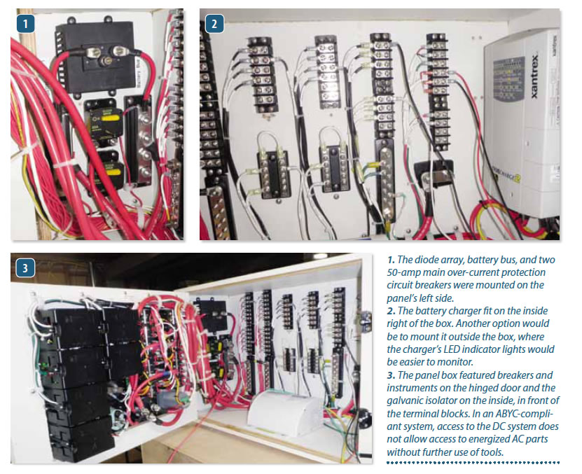
Built in 1984, Moonshuttle is a 41-foot Irwin ketch with a center cockpit. She has sailed up and down the Eastern seaboard several times. Over the years, the circuit breakers in Moonshuttles original electrical panel stopped working, and replacements were no longer in production.
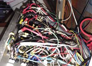
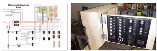
The electrical panel is located under the center cockpit and above the engine compartment. Like almost all boats, this location came with size constraints, but it also had possibilities.
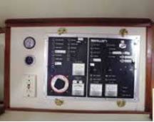
After some research, we realized that a purchased panel would be built better than anything I could construct in my home workshop. The plan was slow in developing, but it came together over three years. This involved documenting the existing panel, drawing up the dimensions of the location, defining the maximum dimension available, and then establishing what was needed on a new electrical panel.
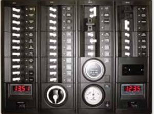
The existing electrical panel had a birds nest of unlabeled wires, typical of older cruising boats. Adding to the identification issue, both the 12-volt DC and the 120-volt AC wires lacked the present-day color-code system (red and yellow for 12 volts DC and black and white for 120 volts AC), so they were all either black or white, making it hard to distinguish between DC and AC wires.
Step one was to list the 12-volt DC and the 120-volt AC circuit breakers on the original electrical panel, then make a second list for the new panel with spare circuit breakers. This included adding a 30-amp circuit breaker for a future generator, a transfer switch, and spare circuit breakers for future projects. The transfer switch would allow either a 120-volt AC, 30-amp generator or one 30-amp shore power source to feed both the port and starboard 120-volt AC busses.
The next step was to develop an electrical single-line drawing of the existing panel ,and then change it to include the upgrades needed for the new panel.
We found two reputable marine electrical panel vendors, Paneltronics and Blue Sea Systems, both of which have gotten good marks from Practical Sailor in the past. From the single-line drawing and a list of the AC and DC circuit breakers, we created a list of requirements and sent this out for quotes. Both vendors were excellent to work with, and each produced designs with similar cost structures using computer-aided design (CAD) software. A spreadsheet compared the individual pros and cons to help analyze the trade-offs. We noted that neither vendor had a transfer circuit breaker. The Paneltronics design came with hinges, allowing easy access for service, but it was too large and would not fit the same space as the old panel. The Blue Sea Systems panel design did not have hinges, but it fit. After some thought, we decided that the smaller Blue Sea panel could be mounted on a hinged wooden door that we could build.
After several design iterations with both vendors, we settled on using Blue Sea Systems. Blue Sea Systems worked with us in designing the panel but would not sell direct, so it was purchased through a local distributor. Once we placed the order, the panel took six weeks to manufacture and deliver. At the time, a 120-volt AC outlet was not available for the panel so a blank space was left for it. Blue Sea supplied the outlet a month later, and we added it during the assembly process.
Blue Sea also supplied a CAD drawing of the back of the panel that identified the wiring by color. This was very useful in creating a D size wiring diagram using Microsoft Visio software. The wiring diagram included terminal blocks, lugs, DC shunt, and wiring labels that followed the same arrangement pattern as the panel circuit breakers.
It was not possible to mount the new panel in the same location without resulting in a birds nest of wires crammed into a tight space. Instead, we decided to mount the new panel in a box that would extend out from the existing location and then use terminal blocks for connecting to the existing wiring.
We built a prototype mounting box to check the fit of components and the panel hinge. To save cost, the prototype box was made out of 3/8-inch interior plywood and mounted to a base that allowed clamping to a table for assembly. The prototype box was sized to house the battery charger, galvanic isolator, alternator charging diodes, and the 12-volt DC and 120-volt AC terminal buses.
When we were placing the components, we discovered that the existing battery charger failed to regulate properly. This, we realized, was probably why our house batteries had not lived up to our expectations.
The replacement battery charger was a little wider and needed more space. The finished box was made from -inch sign board, a high-quality plywood that is designed for exterior use but is less expensive than marine plywood. The box and hinged door were assembled using stainless-steel nails and water-resistant adhesive. Then, the box was covered with a Formica laminate that matched the boat laminate.
The Blue Sea design used the preexisting fuel and diesel-engine run time gauges, which were easily installed in the new panel. This ensured that the engines measured run time was not affected.
The auctioneering diode array (used to manage two or more DC inputs), battery charger, circuit breakers, galvanic isolator, and terminal boards were installed in the box.
To enable the panel door to swing with minimum stress, the interior wiring to the panel ran parallel with the hinge, so the wires would twist during opening and closing but not bend.
After the panel was wired, it was checked with an ohm meter to ensure there were not any opens or shorts.
The panel was then connected to a 120-volt AC outlet, and a 12-volt DC battery was used as a load for the battery charger. The DC shunt was connected on the 12-volt DC battery negative feed. When installed in the boat, the battery cables used No. 1 AWG cables, but much smaller wire was used for the bench test.
For easy mounting, routing holes were drilled in the back of the new electrical panel box, and a template was made from the routing holes. Using the template, routing holes were then drilled in Moonshuttle, where the new panel would mount.
When we removed the original electrical panel, we were sure to label each wire. The new panel was deeper than the existing one, so the wires in Moonshuttle were extended, color coded, and labeled again. The 12-volt DC wires were color-coded red for positive and yellow for negative, and the AC wires retained their black, white, and green colors when extended. The extra wire lengths were trimmed, coiled with tie-raps, and secured in the void behind panel location.
The completed new panel weighed 80 pounds, which was too much to lift into the boat without help. Therefore, lifting hooks were installed on the top of the panel box. The panel was lifted up to the weather deck using the main halyard with help from the crew at Fairview Marina in Pasadena, Md.
Once it was on the boat, we discovered a slight installation issue: The new panel did not fit! The height dimensions were measured on the port side, but the starboard side, which was slated for installation was 3/8-inch shorter. The problem was resolved with a liberal amount of liquid soap and a lot of pushing.
We also had to remove an old overhead cabin light to allow clearance to open the panel door, and we later replaced it with a low-profile LED lamp.
Once the new panel box was secured in place, we pulled the wires through the holes in the back of the box, labeled a third time, and wired up to the mating terminal blocks. We then replaced the battery cables and installed the DC shunt. After all of the wires were connected, we checked the unit again for opens and shorts. The 12-volt DC was applied using the boat batteries and the 12-volt DC loads were powered up. The 120-volt AC shore power was then applied to the panel, and we confirmed that the 120-volt AC loads were operational.
This was the end of a very long project, but once completed, it allowed for many more projects that were dependent upon electrical power and adequate fault protection.