Over the past few years, weve noticed a worldwide uptick in keel failures. The problem has yet to reach epidemic proportions, but we are hearing more and more troubling accounts of what happens when the ballast parts company with the hull, and a crew faces capsize, flooding, and-all too often-death.
The number of incidents speaks for itself. When the International Sailing Federation (ISAF) formed a working group in 2013 to look into the keel loss issue, it tallied up 72 incidents (since 1984) that resulted in 24 deaths. Far from complete, this profile records only incidents where survivor reports or vetted secondhand accounts were available, or where vessel remains pinpointed keel failure as the cause of a loss. No numbers exist for cases in which sailboats simply disappeared at sea. Keel failure, resulting in major hull damage and loss of stability, certainly can’t be ruled out in those cases.
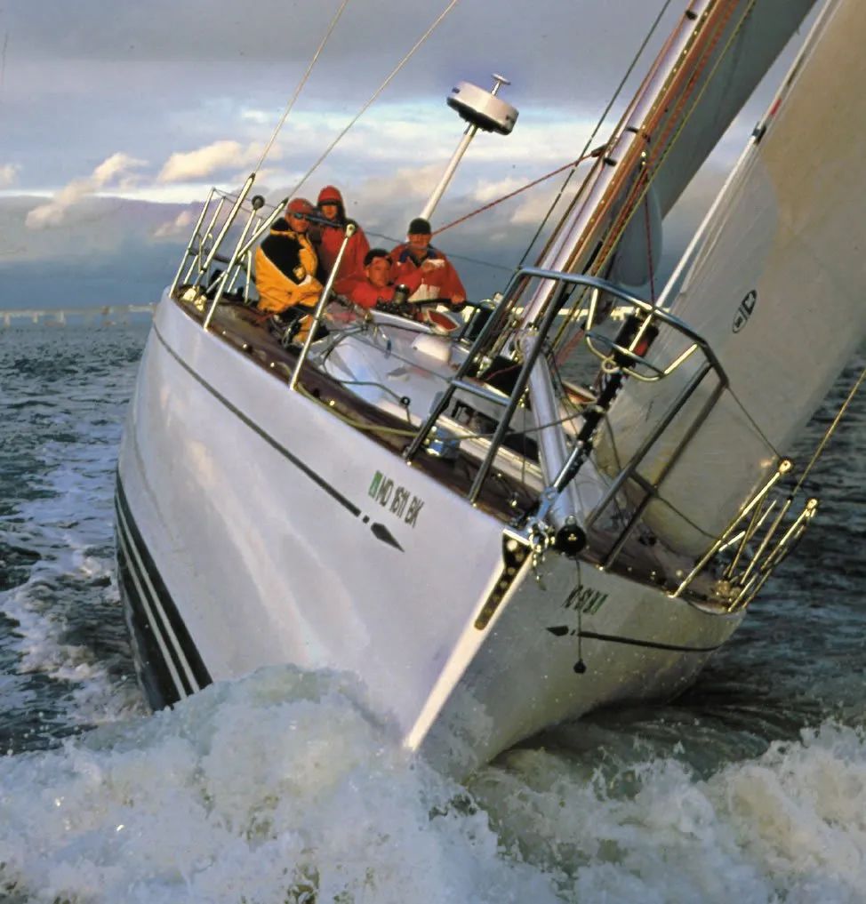
Photos by Ralph Naranjo
Its often hard to come by detailed information portraying what actually went wrong due to litigation and the regular use of gag orders that hold back the details and protect certain parties involved in the litigation. The much larger automotive and aviation industries attract more scrutiny and regulatory control, and product failures gather greater attention. But when it comes to keel failures, mums the word. So whos keeping track?
In the U.S., theres a long list of players who have a role in determining how well (or poorly) recreational boats are built. Theres the National Marine Manufacturers Association (NMMA), American Bureau of Shipping (ABS), American Boat and Yacht Council (ABYC), the American Boat Builders and Repairers Association (ABBRA), the Society of Naval Architects and Marine Engineers (SNAME), several marine surveyor organizations, and the U.S. Coast Guard, just to name a few. And to the credit of many of these august institutions, the topic of sailboat keels has not been ignored. However, in contrast to the Europeans effort to define keel attachment scan’tlings via ISO 12215-9, theres no apparent rush in the U.S. to better define structural standards for keel attachment. The ABS published the 1994 Guidelines for Offshore Racing Yachts, which incorporated some valuable specs defining scan’tlings (the dimensions for structural components) and engineering approaches for attaching the ballast to the hull. For example, where keel bolts penetrate the keel stub or canoe body of the hull, the laminate should be a minimum thickness equal to the diameter of the keel bolt. Even to the casual observer, this specification hardly seems adequate, especially in light of the radical, long bulb keels we see today. As it turns out, many of the recent keel failures reveal hull and keel stub laminates that fail to meet the 1994 ABS guidelines for thickness. How did these boats even make it onto the market?
From Paper to Production
Every naval architect quickly learns the peril of what can happen when a completed boat bears little structural resemblance to the boat he or she designed. Due to the nature of the boatbuilding business, design specifications often vary from the finished product specs. Seldom is a change for the better.
In the past, the naval architect or yacht designer was closely involved in the production of his design, often presiding in the boatyard during the building process. Those days, unfortunately, are long gone. It is only natural to wonder who oversees how the vessel is built today, and how the devils details are excised.
Currently, its not unusual for a boat builder to purchase the plans of a favored design and then take over the development with their own rendition of engineering specs. Vital issues such as the laminate schedule, which varies throughout the boat, must be applied according to engineering specs during the molding process. Loads vary in different parts of the boat, and structures that support the ballast keel must handle huge bending moments coaxed by wind, wave, and gravity. Top-quality builders carefully monitor the unit count of fiber reinforcement and resin volume used, pay heed to minimizing void content, check cure time and temperature, and confirm resin hardness. Some builders hire composite engineering firms that will gladly provide laminate plans that identify the specific fiber type, number of layers, core material, and resin used in specific regions of the boat. Most hull and reinforcing grids are built in female molds and later bonded together. The composite experts are often on hand to make sure that all goes as planned and that the secondary bond joining these components is as void free as possible.
But building shortfalls do happen. In one case, a new, 44-foot Tartan sloop was beating to windward as the cabin started to fill with seawater. The boat had started to split down the middle, the result of the builders laminating crew deciding to use a butt joint at the centerline rather than overlapping each layer of fiberglass.
A 36-foot boat serviced by PS Technical Editor Ralph Naranjo at the boatyard he used to manage clearly illustrated the problem with contemporary keels. The boat had a deep keel sump and bolt-on external ballast. Just out of curiosity, Naranjo had the travelift operator step down, and with the vessels keel suspended a few inches above the ground, the operator and Naranjo took turns putting pressure on the end of the keel with their feet. Immediately, the suspended, lead-ballast keel began to move back and forth. This minor can’ting caused the hull to dimple with each sway. The owner agreed with Naranjos suggestion that they add transverse framing in the sump and more laminate at the turn of the bilge.
Sailboat design has evolved over the years, and higher performance underbody configurations are definitely playing a role in many of the keel calamities we hear about. A few decades ago, a sailboats keel was designed to be contiguous with the hull, and the ballast could be external (bolted on) or internal (encapsulated in a keel/hull monocoque structure). The interface between the ballast and the hull extended fore and aft for a greater distance than its root-to-tip measurement.
Today, many race boats and performance cruisers incorporate a very different design paradigm. One of the contributing factors in keel vulnerability is that modern keel designs are like a lever that keeps attempting to split the hull in two. Naval architects responding to a demand for better upwind performance have turned to keel shapes that are optimized for lift and righting moment, making them look like tongue depressors with a bulb of lead at their base.
The big challenge lies in how to attach such a lever-like appendage to the hull and to transfer the loads away from the point where the fin root meets the hulls canoe underbody. The good news is that it can be done. The bad news is that the best material to use is the proverbial unobtainium-a strong, stiff, light, isotropic fiber-rich polymer that has yet to be invented. So the next best alternative is a tapered, grid-like reinforcement near where the keel meets the hull.
In the area where the keel meets the hull, skin thickness is increased, core is left out, and stiffness is achieved through the addition of internal structure. Any effort to save further weight in this region is like putting less carbon-dioxide in a fire extinguisher so it will be a little lighter. Somewhere along the way, boatbuilders and designers seem to have lost sight of the fact that this is the part of a boat where structural overkill is totally acceptable.
The quest to make racing sailboats lighter and stiffer has resulted in more and more of the laminate ending up as grid or other longitudinal and transverse support rather than hull skin. The net result is a thinner-skinned shell and a more rigid skeleton.
This paradigm was tried decades ago by the Kiwis and Australians who designed and built thin-skin, wood/epoxy hulls and stiffened them with aluminum-tube geometric shapes running fore and aft and linking to points where the keel, maststep, and chainplate loads were focused.
New Zealand designer Paul Whiting, a pioneer of ultralight, thin-skin racing sailboats, was lost at sea during a Sydney Hobart race when a Tasman Sea storm presumedly caused massive structural damage to his sloop Smackwater Jack. Similar hull failures occurred aboard around-the-world racing boats, and these data points led designers to reconsider scan’tlings and develop a better feel for how the dynamic impacts of a seaway influence structural decisionmaking.
Today, finite element analysis (FEA) and engineering software help guide designers. These new analytical tools allow boat designers to specifically locate the hotspots where the tug-of-war between righting moment and heeling moment act out their battle. Variables like wave impacts and sudden gusts can be modeled, but unlike the aviation industry, which does a superb job of keeping wings attached to aircraft, sailboats all too often develop keel woes. However, as a naval architect recently reminded us, most pilots arent running their wing tips into mountain peaks, and there are no sandbars in the sky. In other words, the sailboat-building industry is under-estimating the net effect of running aground.
The Engineers Perspective
Philosophers and engineers have an affinity for first principles reasoning. In lay terms, this means drilling down to the fundamental reasons why something holds together physically or how reasoned thought springs from observable fact. When it comes to keels, the engineers first principles focus on using numbers to define stress and geometry to show how forces impact structure. The engineers goal is to be able to quantify the energy transferred through the hull, rig, and appendages, and to respond to the empirical data with structures that can handle the load.
When it comes to external-ballast keels, there are several points where key connections are made. The ballast itself is usually lead or iron, and mechanical fasteners are used to secure it to the hull. Or ballast may be attached to a keel stub or blade-like foil before being attached to the hull.
Keels with higher aspect ratios (depth to length) and longer lever arms focus more force on the surface area of this critical junction. The person doing the engineering must juggle multiple factors at once. The ballast weight, the distance of the ballasts center of gravity from the critical keel-to-hull joint, the laminate schedule, the reinforcing structure, and the mode of fastening make it a multivariate challenge.
Lets start with the question of ballast material and its role in keeping the keel attached to the boat. Lead is still the ballast material of choice because of its density and the relative ease with which it can be cast into a hydro-
dynamic shape. But a few builders and boat owners have learned the hard way that pure lead is too malleable and may even allow keel bolts to pull free. Consequently, foundries that make keels have perfected an alloying process that involves adding a small amount of antimony (about 4 percent) to the lead to make it less malleable and more willing to hold both keel bolts and its shape.
Monel is the best metal to use for keel bolts due to its strength and corrosion resistance, but it is cost is prohibitive, so 316 stainless steel or even silicone bronze are good alternatives. It makes good engineering sense to offset keel bolts rather than run them down the centerline. The working rule of thumb is to keep the outer wall of a keel bolt at least an inch under the lead surface and far enough down in the ballast to prevent it from being pried from the ballast.
Care must be taken when casting a keel to make sure that the keel bolts, and any weldment used to hold them in place, are preheated prior to the pour so that theres no chance of bubbling around the colder metal. These bubbles become voids than can trap water and cause corrosion problems. Thanks to good quality control at keel-casting companies, failures caused by keel bolts pulling out of cast lead are less prevalent today.
Keel-bolt metallurgy is another factor, and its a two-part story. Part one is all about the tensile strength of the material and what kind of out-of-the-box safety margin the bolts will deliver. The second part is about lifespan and corrosion resistance.
Every time a sailboat tacks or rolls in a seaway, keel-bolt loads swap from side to side. This on/off, tension-fatigue cycling causes changes in the metal at a molecular level, and some alloys are better than others at handling this type of cyclical loading. Of equal importance is the manner in which the ballast and hull surfaces mate. Imperfections in how the two surfaces make contact will result in uneven loading and even a perceptible wobble in the joint as gravity pulls the ballast from one side to the other. Simply filling minor voids between the keel and hull stub with a sealant is a big mistake. In cases where the surface-to-surface contact is imprecise, a high-density epoxy-filler repair should be carried out so that surfaces are both smooth and fit together precisely. (See PS Advisor, January 2008.)
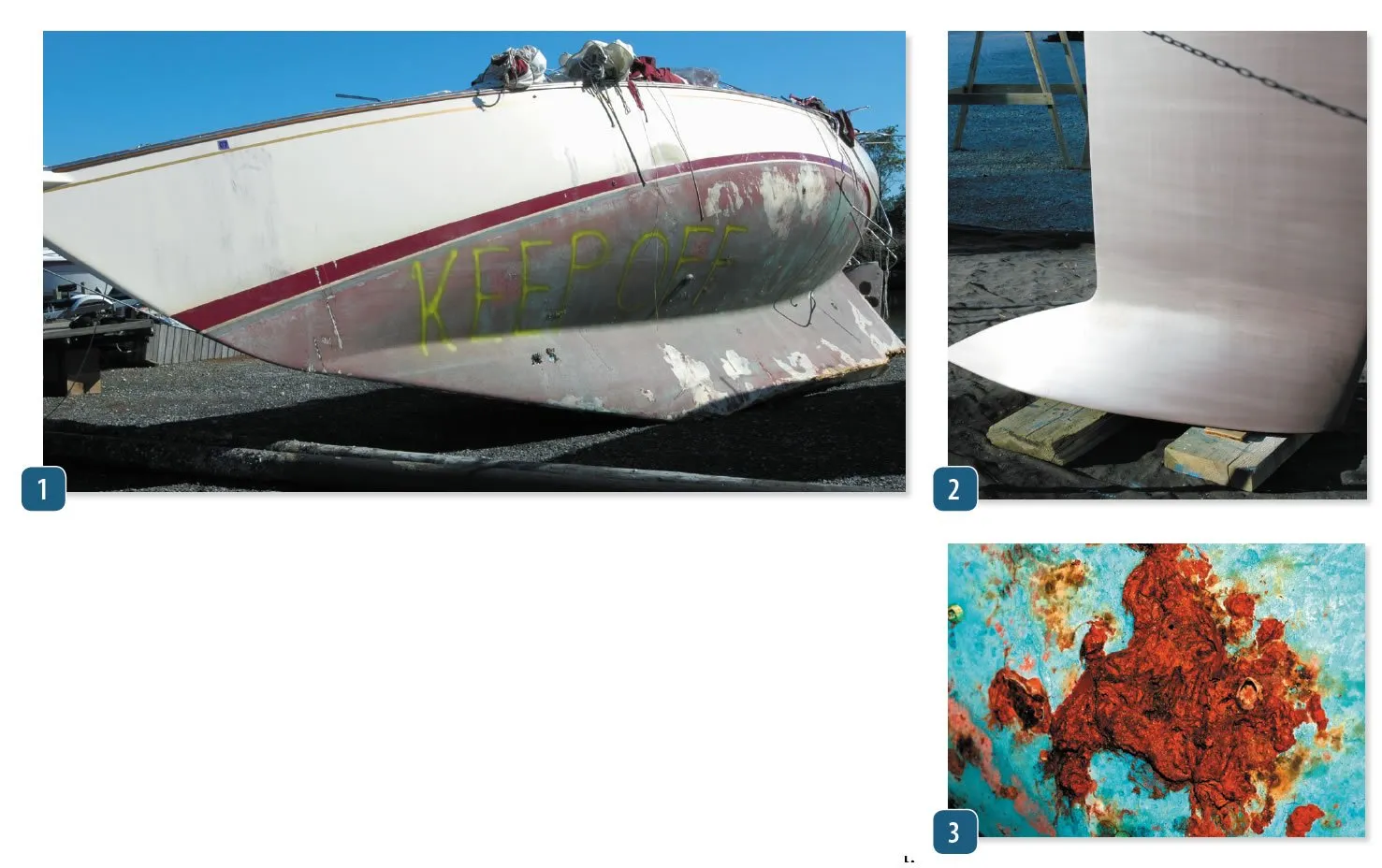
Many production-boat builders opt for iron ballast and galvanized, high-carbon steel keel bolts. This is a cost-saving shortcut that, down the road, leaves an owner coping with rusting ballast and the ticking time-bomb of corroding keel bolts. Those buying a decade-plus-old, pre-owned sailboat with high-carbon steel keel bolts and iron ballast should consider having a good boatyard lower the ballast and carefully inspect the bolts. Simply torquing up the fasteners and heading off on a long ocean passage on a boat of this vintage is courting an unnecessary risk.
Some rust on keel bolts is to be expected, but how much is acceptable depends on how oversized the bolts are, how many hold the keel to the hull, and how long and wide the ballast-to-hull seam happens to be. Stainless-steel keel bolts arent totally immune to seawater chemistry, but high-nickel-content 316 stainless steel has a fine track record, as do silicone bronze keel bolts, keeping in mind that silicone bronze bolts must be slightly larger in diameter to deliver the same tensile strength.
Theres one keel usage where rust-prone carbon steel is gaining ground and its use makes sense. Its in radical race-boat fin/bulb keels where stiffness counts and deeper, thinner, shorter chord foils are the trend. In such situations, carbon fibers lighter weight isn’t a big advantage and high-tensile steels stiffness combined with its hardness and toughness are ideal for making mechanical junctions at each end of the foil. Slots in ballast bulbs and carefully engineered keel boxes built into the hull are costly, esoteric parts of many modern race boats. During the design process, much care is given to spreading the loads focused on these socket-like fixtures, and energy moves transversely across the hull and forward and aft via a network of frames and stringers.
Most production boats have a simpler solution for handling keel-bolt loads. In the era of wooden boats, floor frames and the keelson did a lot to dissipate ballast loads. Fiberglass changed some of the engineering. In the 1960s, solid fiberglass-reinforced plastic (FRP) laminate hulls with thickly laid-up keel sumps could easily cope with the loads from the long, shallow, ballast keel common for that era. As laminates grew thinner, core material spread throughout the hull and keels grew deeper but shorter fore-and-aft, attachment problems proliferated. Better engineering was on hand to offer solutions.
The modifications included keeping core material away from the critical interface where the ballast keel or keel stub met the hull. Another change was the introduction of grid structure to stiffen the hull so that it would reduce the bending moment induced by the keel. Cruisers were happy with the belt-and-suspenders approach of a thick hull skin and a strong grid. This increased the safety factor when it came to how well a keel was attached.
Racers, however, wanted a stiffer, lighter hull, but at the same time, they recognized that in order to win, one had to finish the race-which, of course, required keeping the keel and hull intact. Over the years, builders and designers have seen a proliferation of cautionary tales of what happens when this quest for a fast, light boat overshadows the sanctity of the keel-hull joint.
A key design consideration is the load imposed on the hull in a knockdown, when the mast is parallel to the water. In a knockdown, the loads at the point where the hull and keel meet skyrocket, especially when theres a bulb of lead at the other end and a very small area where the keel meets the hull. If the sailboat has been carefully engineered, the designer has calculated what this peak load will be and then chosen a healthy safety factor to hedge his or her bet. This safety factor will go a long way in accounting for some material deterioration due to minor corrosion, fatigue, or some other unforeseen situations.
The bible for many naval architects and sailboat designers is The Principles of Yacht Design (PYD) by Lars Larsson and Rolf Eliasson. And when it comes to the crucial links in keeping the ballast attached, the authors justifiably put much stock in hedging a bet. When it comes to keel-bolt diameter and floor-bending moment, they recommend a 5-to-1 safety margin. The less stringent ISO 12215-9 equations settle on a 2-to-1 safety factor for bending moment in category A and B vessels. But the wild card is not the sailing loads, which are quite definable; its the point loads linked to groundings and the ongoing weakening effect of cycle loading and corrosion.
The ABS guidelines mentioned earlier take a harder line when it comes to structure that mitigates grounding damage. It has the most stringent laminate thickness and core elimination requirements. Other classification scan’tlings diminish the projected loads of a grounding. They regard the inertial rotation of a hull as a means of significantly offsetting the stress of a grounding. The ISO guidelines, for example, take this into account. The result is a force of impact that is much lower than that envisioned by the ABS, which ignores the effect of inertial dampening during a grounding.
All this keel theory came into play two years ago, about 720 miles east-southeast of Nova Scotia, Canada, with the tragic loss of Cheeki Rafiki and all hands aboard. The incident occurred during a return passage to England from the Caribbean. The eight-year-old Beneteau 40.7 was in the charter trade as a race boat, and records revealed that it had been campaigned regularly in the United Kingdom during summers, in trans-Atlantic ARC races, and in Caribbean winter regattas between 2011 and 2014. On May 16, 2014, Cheeki Rafiki lost its keel and capsized in the cold North Atlantic; the life raft was apparently unable to be deployed. The Beneteaus upturned hull was later spotted by a merchant ship, and photographs revealed that some of the keel bolts, with nuts and washer plates in place, had pulled through the laminate and others had apparently snapped, leaving threaded rod, nuts, and washers behind.
According to the incident review done by the Marine Industry Accident Review Branch (MIARB), United Kingdom, the Farr-designed sloops had their structural details finalized by Beneteau. Beneteau indicated that the boat was designed to ISO A category standards and structural approval was made by Bureau Veritas. In the MIARB report, the University of South Hampton (Wolfson Unit) evaluated whether or not the Beneteau 40.7 would meet ISO 12215-9 criteria, which was not available when the boat was built. The reports conclusion was that the as designed parameters would meet the vast majority of structural requirements spelled out in the ISO 12215- 9 standard. However, according to the report, the keel washers did not meet the standard. Perhaps more tellingly, the standards did not allow for the elimination of a 24-millimeter keel bolt that should have been at the aft end of the keel.
The university report also commented on whether or not a change in grid stiffness caused by two previous repairs could have altered the grids load-spreading characteristics. In essence, investigators looked into whether or not a hard spot in the grid could have resulted in a stress riser that refocused loads and led to an area that was more prone to failure. Their finding was that the same FRP materials had been used in the repair, and it did not change the grids load-sharing characteristics.
Conclusion
Several things in the Cheeki Rafiki report stood out to us. First, its interesting to note the difference between the ABS minimum guidelines for skin thickness where keel bolts penetrate an FRP structure and the ISOs minimum. The ABS spec calls for a laminate thickness equal or greater than the diameter of the keel bolt. ISO guidelines call for a minimum of 9.1 millimeters. The Beneteau 40.7 had a hull skin thickness of 7.7 millimeters and made up for the shortfall by adding in the thickness of the stiffening structure, which was actually thicker than the hull itself (10.5 millimeters) but connected to the hull skin via a secondary bond. The total thickness, by this accounting, was 18.2 millimeters, but this is still less than the ABS minimum of 24 millimeters. Perhaps a thinner skin would be appropriate if the builder had been using a high-modulus, vacuum bagged, prepreg carbon-fiber laminate. (Prepreg laminate is pre-infused with resin to ensure a strong, lightweight laminate that has a high fiber content.) But the 40.7 was built using traditional wet layup, which results in a lower fiber content and a lower-strength laminate.
The report delves into Cheeki Rafikis reported groundings and associated repairs. This section of the report leaves readers wondering whether ISO-compliant keels are too fragile. The ISO A categorization assumes correctly that all bets are off if you go and sail into the maw of a major hurricane, but should a relatively soft grounding render the hull a hazard?
The old Cal 40, Ericson 41, and plenty of 50-year-old Rhodes Bounty IIs still safely lug around their encapsulated-ballast keels. These designs have clearly stood the test of time. Well-designed and engineered, externally ballasted keels should be even more able to handle transverse and longitudinal loads, including the odd soft grounding.
One important consideration is the nature of the ISO ratings. PS has argued for years that the ISO rating is a standard meant to facilitate fair trade, not a benchmark for good design. Among the members of the ISO working group that came up with the standard were boatbuilders who had an interest in a broadly inclusive Category A standard.
In several instances, the standard for keels would prompt an engineer to question the rationale behind the rules. Take for example the fact that when it comes to keel attachment, the ISO 12215-9 specification lumps Category B and Category A vessels together. But when it comes to stability requirements, ISO recognizes that a Category A vessel will be exposed to more hazardous oceanic conditions, and therefore, will need greater stability. Why didnt the same seafaring logic prompt ISO to make the keel attachment scan’tlings for Category A sailboats more stringent than they are for Category B? Its not unreasonable to assume that ocean-crossing sailboats need higher keel attachment standards than boats designed primarily for coastal sailing.
Boat shows slips are brimming with production boats rated Category A, but does the label really mean they meet the challenge? Cheeki Rafiki was sailing in conditions well within the wind and sea state couched in Category A. The keel snapped off, and the crew perished. The Action to be Taken section in the MAIRB report includes a warning about minor groundings, painting the rudder day-glow red, placing the life raft in a spot that enables launching even if the hull is overturned, training the crew about capsize and inversion, and finally, it recommends that the ISO insert the text, in case of grounding, a full assessment/survey needs to be completed. We were surprised, if not shocked, to see that there was no mention of designing and building a stronger keel attachment, and no suggestion that the current scan’tlings for Category A vessels needed to be re-examined.
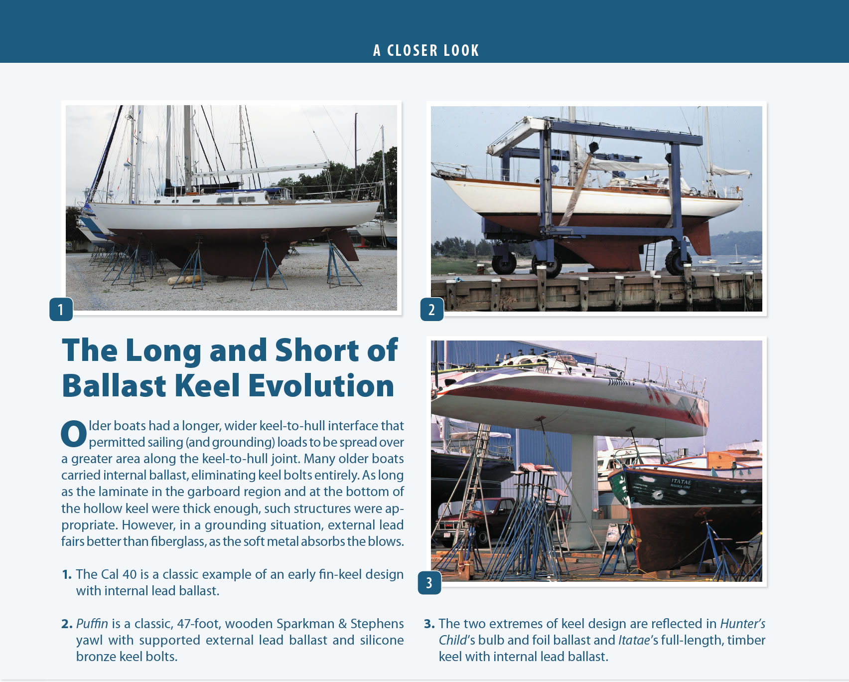
Older boats had a longer, wider keel-to-hull interface that permitted sailing (and grounding) loads to be spread over a greater area along the keel-to-hull joint. Many older boats carried internal ballast, eliminating keel bolts entirely. As long as the laminate in the garboard region and at the bottom of the hollow keel were thick enough, such structures were appropriate. However, in a grounding situation, external lead fairs better than fiberglass, as the soft metal absorbs the blows.
- The Cal 40 is a classic example of an early fin-keel design with internal lead ballast.
- Puffin is a classic, 47-foot, wooden Sparkman & Stephens yawl with supported external lead ballast and silicone bronze keel bolts.
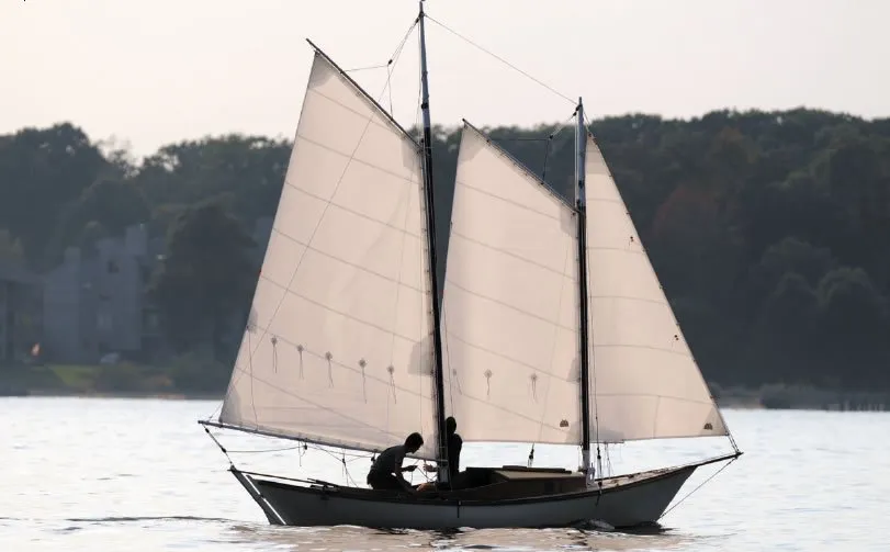
- The two extremes of keel design are reflected in Hunter’s Child’s bulb and foil ballast and Itatae’s full-length, timber keel with internal lead ballast.
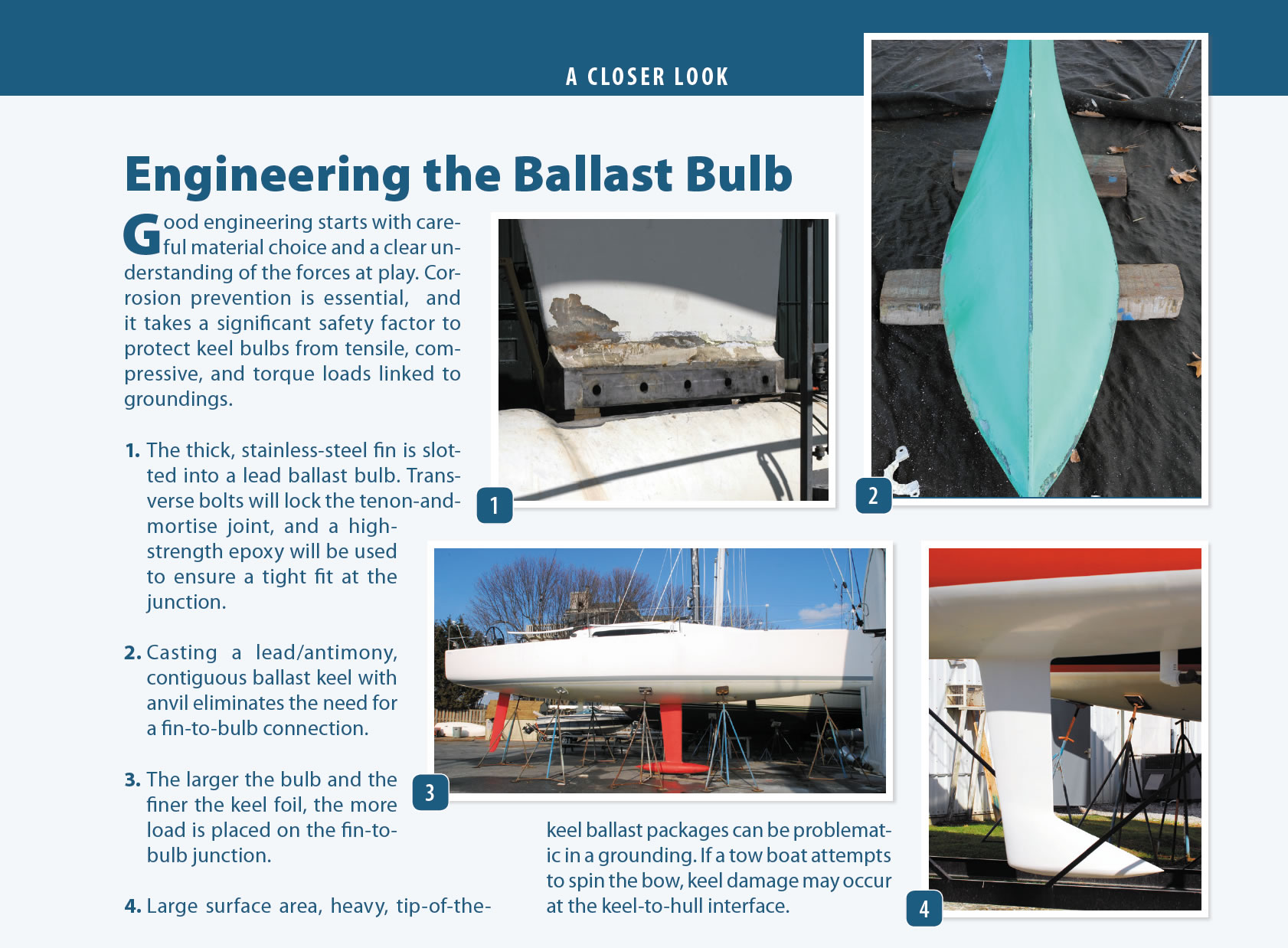
Good engineering starts with careful material choice and a clear understanding of the forces at play. Corrosion prevention is essential, and it takes a significant safety factor to protect keel bulbs from tensile, compressive, and torque loads linked to groundings.
- The thick, stainless-steel fin is slotted into a lead ballast bulb. Transverse bolts will lock the tenon-and-mortise joint, and a high-strength epoxy will be used to ensure a tight fit at the junction.
- Casting a lead/antimony, contiguous ballast keel with anvil eliminates the need for a fin-to-bulb connection.
- The larger the bulb and the finer the keel foil, the more load is placed on the fin-to-bulb junction.
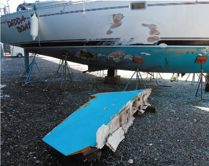
- Large surface area, heavy, tip-of-the-keel ballast packages can be problematic in a grounding. If a tow boat attempts to spin the bow, keel damage may occur at the keel-to-hull interface.
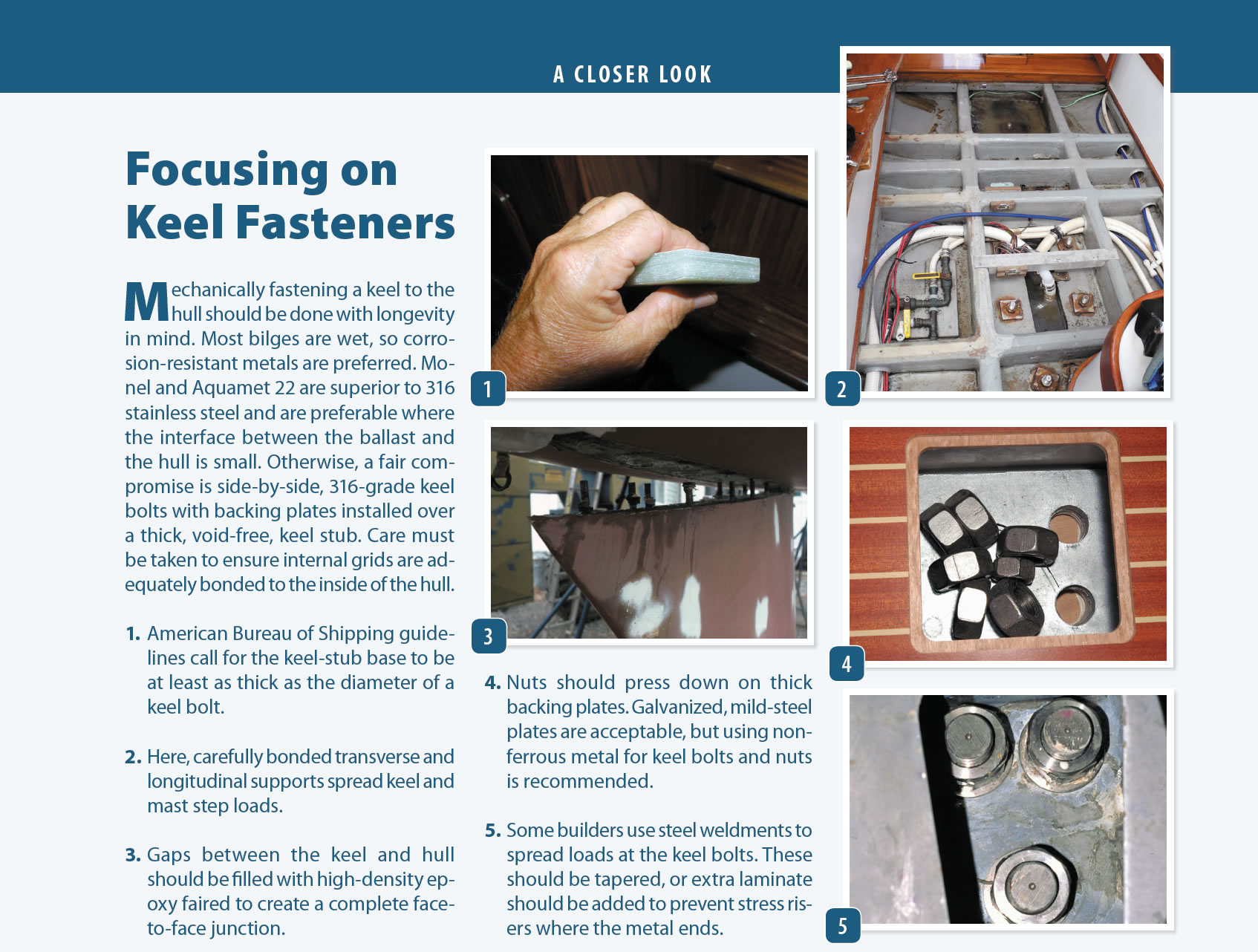
Mechanically fastening a keel to the hull should be done with longevity in mind. Most bilges are wet, so corrosion-resistant metals are preferred. Monel and Aquamet 22 are superior to 316 stainless steel and are preferable where the interface between the ballast and the hull is small. Otherwise, a fair compromise is side-by-side, 316-grade keel bolts with backing plates installed over a thick, void-free, keel stub. Care must be taken to ensure internal grids are adequately bonded to the inside of the hull.
- American Bureau of Shipping guidelines call for the keel-stub base to be at least as thick as the diameter of a keel bolt.
- Here, carefully bonded transverse and longitudinal supports spread keel and mast step loads.
- Gaps between the keel and hull should be filled with high-density epoxy faired to create a complete face-to-face junction.
- Nuts should press down on thick backing plates. Galvanized, mild-steel plates are acceptable, but using non-ferrous metal for keel bolts and nuts is recommended.
- Some builders use steel weldments to spread loads at the keel bolts. These should be tapered, or extra laminate should be added to prevent stress risers where the metal ends.