Practical Sailor editors have noticed the increasing tendency in newer-model sailboats to be ill-mannered in gusty conditions. Establishing balance between the sails and the hull is one of the main factors in quality boat design. For correct trim, many things must be considered: the ballast package location, the combined longitudinal center of gravity (LCG), and the longitudinal center of buoyancy. At the same time, to maintain a balanced helm, the keel must promote sufficient lead (the fore and aft distance between the center of effort and the center of lateral resistance). To highlight how these boat design principles play out, Practical Sailor looks at classic sailboats such as the Bill Shaw-designed Pearson 32, Ericson 41, Valiant 40, and Peterson 44, and compares their keel/sail ratios and lead values to more modern sailboat designs such as the Catalina, Hunter, Tartan, and Beneteau.
****
In the course of taking out boats for testing, Practical Sailor editors have observed an increased tendency for new-model sailboats to be ill-mannered in gusty conditions. We have been watching this trend for several years, and it seems to be becoming more usual than unusual.
In a typical situation, we will be sailing the test boat on the wind in 12 or so knots of breeze and everything is fine. Then, the breeze picks up to about 15 knots and the helm loads up. OK, thats to be expected, so we flatten the main, drop down the traveler, and that takes care of it.
Then we get a puff. Were already on the point of needing to reef, so in the puff, were overcanvassed. Instead of just heeling farther, the boat begins to round up. Fighting it with the helm is hard work, and easing the main so it luffs doesn’t help much.
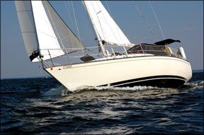
Photo by Ralph Naranjo
We take in a reef, which usually means we roll in a bit of the jib or a bit of the main, or both, and the helm lightens up. We trim to the new wind and sail along, a bit slower now in the light spots, but then the next gust comes along, and the helm immediately loads up again.
In the worst case weve experienced, the boat rounded up so quickly that it tacked, even though the helm was hard over in the opposite direction. To prove that wasnt a fluke caused by a temporary diversion into a parallel universe, it did the same thing on the other tack.
Practical Sailor editors are old enough to remember a generation of cruising boats that didnt behave in this manner. For sure, there have always been twitchy boats, but most, when hit by a gust, would heel a little more, put some pressure on the wheel or tiller, and once the boat picked up speed, the pressure would come right off. A boat like that will sail for a long time with a loose lashing on the helm.
So, where does this bad habit come from? Several trends in modern cruising yacht design can share the blame. One of them is builders inclination to tilt their designs toward the performance end of the cruisers spectrum. Many recent and current cruising boats, if suitably fitted out with racing sails and the hardware and software to tweak them, could put up an impressive show on the race course.
The sensitivity to trim that accompanies such potential isn’t always suited to cruising shorthanded or with a family, when balance and good manners are key both to enjoyment and, to a degree, safety.
Establishing Balance
Many factors contribute to the balance of a sailboat. The obvious and principal pair are the sails and the hull. When working up a new design, the architect develops these in close association, but both are in turn influenced by other aspects of the boats design as it evolves.
In the standard approach, the designer works up preliminary drawings to express the basic requirements of the design brief, which normally include a desired length, displacement, cabin arrangement, and sailplan to provide the desired performance.
He then sketches out the hull lines (the matrix of contours that define its three-dimensional shape and its volume) to enclose the interior and meet expressed performance goals. The preliminary lines also serve as a basis on which to perform a number of calculations, one of them being the location of the center of buoyancy (CB).
With everything roughed out, the designer then “weighs” every item that will go into the complete boat, from the hull laminate to the toothbrush holder, but excluding the ballast. He combines these weights and their locations on the three axes, X, Y, and Z, to calculate the center of gravity (CG) of the whole package. Computer programs have helped to speed up this process and make volume calculations more accurate, but the process hasn’t changed much.
For the boat to float on its desired lines, the ballast package must then be designed and located to bring the combined longitudinal CG (LCG) of hull and ballast to the same fore-and-aft location as the CB (LCB). Once everything has been resolved satisfactorily, the designer can finalize the lines, carry out the necessary calculations, and establish shape and locations for the keel and the sailplan.
On most boats of current design, the ballast also constitutes the fin keel, and in that role, its location determines the center of lateral resistance (CLR), which in conjunction with the center of effort (CE) of the sailplan, influences how the boat balances under sail.
Even as boat design procedures have evolved from three-dimensional modeling using half hulls, through two-dimensional modeling using pen on vellum, to three-dimensional virtual modeling on computers, the fundamental principles have remained constant. One of the fundamental values used for predicting the proclivities of a boats helm is the dimension termed “lead.” Lead, pronounced “leed,” is the fore and aft distance between the CE and the CLR, expressed as a percentage of the waterline length (DWL).
“Skenes Elements of Yacht Design,” as revised by Francis S. Kinney, and other references for yacht design provide rules of thumb for calculating lead from the sailplan and the hull profile. (See illustration above).
Looking at the diagram, its easy to see how lead is an elusive quantity. First of all, no boat sails with the sailplan as shown-the sails are never flat and on centerline. The traditional range for lead places the CE forward of the CLR by 14 to 19 percent of DWL. This value is lifted from “Skenes,” for years the first reference for any designer. Since that book was written and updated, hull forms have changed, and with them, optimum values for lead.
On designs with fin keels, lead is often calculated with reference to the keel alone. One feature remains constant whatever the design. Moving the centers closer together-reducing lead-increases the tendency to weather helm. Moving them apart reduces that tendency. If the lead is too great, the result may be lee helm, which is generally considered undesirable-and is in fact, rare.
In Kinneys prime years, the 1960s to the 1980s, the basic working sailplan of a sloop included a 150-percent genoa, which would have the effect of moving the CE closer to the CLR. Many designs today have headsails with short or even no overlap and very often a full-battened mainsail with lots of roach. The different aerodynamic characteristics of such rigs might well affect optimum lead, something which designers can only determine through experience. (If a boatbuilder offers an in-mast furling mainsail as an option, its effect on lead will differ from that of the “classic” sailboat.)
The effective CLR can also be very different from that calculated. On a deep-bodied, full-keel hull, that difference simply might be the difference between the geometric center and the center of hydrodynamic pressure of the whole profile.
A sharp bow with a pronounced “chin” might well move the effective CLR forward. On a modern, fin-keeled boat with a shallow, broad canoe body like that of a dinghy, the keel makes a proportionately larger contribution to lateral resistance, so the location of the keel will strongly influence where that resistance operates.
Obviously the rudder, too, is part of the lateral plane, but if our objective is to sail with light to neutral pressure on the helm, under normal conditions, it should not be making a significant contribution to lateral resistance. Its role is to provide a means to change the boats direction and to compensate for the constant fluctuations in the forces applied to the boat in the normal course of sailing. A certain amount of pressure in the form of weather helm helps by providing positive feedback to the helmsman on the state of balance. That said, on many racing hulls, the rudder is designed to contribute lift and has an active role in driving the boat to windward. (It is worth noting that those wide-bodied race boats also tend to have twin rudders.)
Then and Now
Even in the age of computer modeling, yacht design remains a series of compromises. At the moment, it seems the pendulum has swung to a point where high-volume, wide-beam shapes dominate. With them come large rigs to overcome skin drag and its negative effect in light air. As a result, theres a need to sail the vessel as flat as possible or suffer the consequences.
The sailplan and outboard profiles of boats from different eras represent the shift in yacht design that has occurred during recent decades. The modern boats have longer proportional waterlines, indicating higher potential speed. It also means that the boats immersed volume, or displacement, has been distributed over a greater length.
Given two boats of similar displacement like the classic Pearson 32 and the modern Tartan 3400 (above), the Tartan winds up with a shallower canoe body. This also contributes to its being potentially faster and, if both boats had the same draft, would give the keel a slight advantage in span, and therefore effectiveness to windward.
So far so good, but a shallower canoe body forces the cabin sole upward, especially if the belowdecks accommodations are to take full advantage of the wide beam favored in the modern hull. To achieve comparable headroom with its older counterpart, the cabintop has to go up, too, and to ensure sitting headroom on the settees under the sidedeck, so does the freeboard.
Ultimately, the whole deck moves upward. To ensure the boom doesn’t sweep everybody out of the cockpit during an unplanned jibe, the boom too goes up. If sail area is not to be compromised, the entire mainsail goes up, and with it, its center of effort. The bigger the boat, the less pronounced these differences become as the proportions become more relaxed.
Differences are visible, too, between the boats keels; the modern Tartans is smaller in area. While it might be claimed that less wetted surface promises higher sailing speeds in light air, some builders accept a smaller keel to simplify the manufacture of the hull.
In a perfect world, the designer draws a keel to suit the boats sail area and other characteristics, places it to obtain the desired sailing performance, then massages the needed ballast to both fit the keel and trim the boat correctly. The volume of the ballast is usually less than that of the keel, and the builder has to do some intricate laminating work to mold a keel to receive ballast internally or a stub to which to bolt it externally.
On many production boats today, the keels are bolted directly to the bottom of a fair canoe body, a practice which eliminates much labor. The consequence is that the area of the keel is determined by the weight, and therefore the volume, of the ballast. To achieve the desired hydrodynamic properties and mechanical strength-it mustnt bend under the influence of normal sailing loads-a given volume of ballast can be formed into a limited range of shapes. Placing ballast in a bulb at the bottom aids the keels efficiency by creating an endplate effect and raises stiffness by placing ballast low, but it means that the keels lateral plane is sharply reduced.
For a more dramatic representation of how changes in keel design can affect helm balance, compare a Cruising Club of America (CCA) design like the Ericson 41 above, to a modern equivalent with comparable sail area like the Beneteau 46.
When sailing, two boats are subjected to similar forces on the sails. Resisting that side force are the immersed hull, the keel, and the rudder. If the hulls offer similar resistance, the remaining force is shared between the keel and rudder. If one keel is smaller than the other (as is clearly the case here), the effect is to increase the share taken by the rudder.
When the sails are trimmed properly and all is in balance, the rudder will carry a small load. If however, you hit a gust, the rudder must pick up a high proportion of the added side thrust until balance is restored, usually by some adjustment to sail trim.
Simply put, boats of the general modern type are not forgiving in changeable conditions, say, for example when the apparent wind is in the 12- to 18-knot range. At the higher end, youd want to be reefed; at the lower end, probably not.
On a day when you expect the wind to soften rather than harden, youd rather not put in the reef, so that you can maintain speed in the lulls. In the puffs, you want your hands free to ease the traveler and flatten the jib, which is hard to do if the helm is a handful. Compounding the problem on most boats, the mainsail controls are usually not within reach of the helm.
On racing boats, such sensitivity isn’t an issue. On the contrary, sufficient crew are on hand to make adjustments on the fly as quickly and often as needed to keep the boat sailing at her fastest.
Cruising boats are often sailed shorthanded and by crews who are not looking for a constant physical workout. An autopilot might be doing most of the steering, and good balance is helpful in protecting it from having to work too hard-or from being overpowered.
Plan View
Another striking difference between the older and newer designs is visible in the plan (overhead) view. By 1980, cruising-boat hulls were already becoming beamy relative to boats of the 1960s and 1970s. The current trend is to carry the beam aft, so that in the region of the rudder, its as much as 85 percent of the maximum beam, far wider than the 55 percent to 60 percent once considered acceptable. The principal beneficiary of this extra breadth is the boats interior-builders often offer twin double cabins aft where a generation ago they might have squeezed in a quarter berth and a cockpit locker. The cockpit, too, becomes roomier, and the transom, scooped and sculpted, is transformed into a swim platform and dinghy dock.
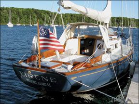
Photo by Jarrod Scanlon
All this additional boat aft adds weight aft, in both construction materials and outfit. To compensate, the ballast-that is to say, the keel-has to be fitted farther forward.
The full beam aft does provide a significant boost to the boats ability to carry sail. As the boat heels, the center of buoyancy moves quickly outboard, away from the center of gravity. This lengthens the righting arm, giving a positive contribution toward stability, but it also moves the immersed centerline of the hull away from the static centerline along which both the keel and the rudder are attached. Depending on the hulls shape, this can create a distortion in the immersed volume, which can in turn affect the dynamics acting on it.
Effect of Keel Area
Another factor entering the equation is the area of the keel. This, too, is apparent when comparing the drawings of the older and newer generation boats. Many of the standard tracts on the design of sailing yachts are, lets say, vague on what keel area is adequate or even desirable, although many designers have come up with their own formulas.
Because the keel is reacting in the water to forces generated on the sails by the wind, it makes sense that the area of a fin keel should be related in some way to sail area.
When naval architect Dave Gerr took over as director of the Westlawn Institute of Marine Technology, he found the course materials for sailing yacht design had little detailed explanation on this topic, a gap he subsequently filled. Briefly, he recommends no fin keel should be less that 2.5 percent of the sail area (mainsail 100 percent foretriangle) and need be no more than 5 percent. The smaller value is appropriate for a racing boat with a full crew aboard to trim and tweak the sails to every change in the wind. The larger area is suited to cruising boats, which need to be more forgiving to shorthanded crews.
Current Design Trends
In the past, racing measurement rules have been criticized because the boats designed to compete under them have become type-formed, sometimes with unwelcome consequences in how they handle. We might just as easily level criticism at present-day marketing and manufacturing methods for doing the same to cruising boats.
Lets face it, but for a few differences in sailplans and keel shapes, modern cruising sailboats are quite generic below the sheerline. They are all beamy; they carry their beam aft; they have long waterlines; they have dinghy-like underbodies; and they have spade rudders. The forces that have created this shape have at least as much to do with how many people can sleep and shower in them comfortably as with how the boats will sail.
Dishing out the hull shape in this manner makes it fairly easy to push through the water, but arranging the keel, rudder, and sails so they work in concert has become a more complex problem, exacerbated by having to compensate for extra weight of accommodations aft, something thats less of an issue in raceboats.
The byproduct of these design parameters is zesty performance, a bonus for the marketing department, but speed for its own sake is not the first priority of cruising sailors. In the brochure for the Beneteau 37, the boats polar diagram shows a maximum theoretical sailing speed of over 12 knots in 30 knots of wind. When cruising sailors encounter 30-knot winds, they are more likely to hunker down in the expectation it will blow even harder than they are to set the chute to go surfing. What they want is a boat that will take readily to hunkering, and all the signs indicate those boats are getting fewer in number . . . and they are mostly older designs.