

This is Part III of a multi-part series describing the rebuilding of our 1982 Cape Dory 36. In Part I (PS November 2022), I described important steps we took to ensure the highest chance of successfully rebuilding our boat. Part II (PS December 2022) described how we went about gutting the interior and then designing and installing a new seagoing interior. In Part III, I will describe why and how we built a new taller rig as well as the many deck projects we completed to make the boat stronger and less complex.
THE MAST
To understand the rationale behind the desire for a bigger rig I need to explain the role of the engine—or in this case the lack of an engine. From the beginning I wanted to rebuild the boat without an inboard engine for multiple reasons.
First, I did not want the underwater drag associated with the original prop aperture which itself could not accommodate a folding propeller, the least drag of all propeller types. Second, installing an offset propeller necessary for a folding propeller required a smaller engine than the original Perkins 4-107. Third, we would save about $15,000 by not installing a new engine, significantly reducing the cost of the rebuild. Fourth, eliminating an inboard engine dramatically simplified the boat by removing the most complex system on board, allowing me to focus my attention on setting the boat up for sailing. Finally, I wanted to get an idea of what sailing a boat this big without an inboard engine really entailed. It’s important to note that I thought I would install an engine someday. I figured I would know it when the time arrived, and thus I had a basic plan for how installing an engine would be accomplished.
Originally, I planned to keep the stock mast and increase the sail area by adding a longer bowsprit. I felt a longer bowsprit would improve the helm and give us more sail area by allowing us to incorporate a bigger jib and a bigger staysail. The original mast had corroded at the heel during its earlier life and I was unsure of its strength. I planned to leave rebuilding the rig till the last phase of the rebuild. But, good fortune came our way and I developed a great friendship with a retired spar engineer. He provided me with the opportunity to acquire a new spar at a substantial savings. I decided the added cost, though small, was worth exceeding our original budget.
Retired Sparcraft engineer Robert Quates and I discussed the requirements for the new spar. I told him I wanted a taller mast for more sail area for several reasons. First, our boat, like nearly all of Carl Alberg’s boats, had a SA/D ratio of about 15.8, which is fine in winds over 15 knots, but underpowered in light wind. A taller mast means more sail area and more sail area increases the sail area to displacement ratio (SA/D) which in turn provides better light air sailing performance.
A taller mast would also eliminate the need for an overlapping jib. A non-overlapping jib is easier to tack, especially in light air. Finally, more sail area would help keep my engineless boat moving, and maneuverable in light wind. Even though I fully expected “someday” I would install an inboard engine, we would continue to benefit from improved light air sailing performance with or without an engine.
CALCULATING SAIL PLAN
To help work out the details of my new sail plan, I purchased Skene’s Elements of Yacht Design and Chapelle’s Yacht Designing and Planning. I read up on the process of designing rigs and sail plans, determining the center of effort and lateral plane, and deciding the lead (the fore and aft distance between the center of effort and the center of lateral resistance) required to achieve a balanced plane (see “Practical Sailor Takes a Look at Trends in Modern Boat Design,” PS February 2009).
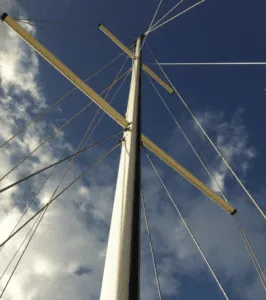
It was not as complicated as it first sounded. I followed the steps, drew the diagrams, and performed the basic math. I decided the SA/D should be around 18-19 and determined a 3.5-foot taller mast with a 4-foot longer luff and a longer bowsprit would do the job. I also liked the way the boat looked with the tall rig and long bowsprit. I thought the longer sprit would reduce weather helm by moving the center of effort forward. I moved the staysail tack a corresponding amount forward to the stem which made for a bigger staysail.
Once I knew what I wanted, I provided the design to Quates and he performed the structural engineering computations to ensure the mast was plenty strong enough for ocean voyaging in any latitude. He chose a lighter, thinner spar section incorporating double spreaders and running backstays to be used when sailing offshore with the staysail.
He accommodated my plan to use hand spliced 7×7 wire rigging. Though the mast was taller and the rigging heavier, with the lighter mast our rig weighed about the same as the original. As an added precaution I asked the well-known rigger Brion Toss to look over the spar design. He recommended only one change—that we terminate the forestay at the upper spreader, about 12-inches below the spot that Quates had designated.
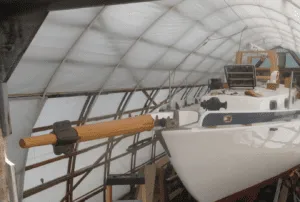
Robert fabricated the spar and provided all the components. I picked up the spar and trailered it home. We hired a painter $200 to spray it with primer and Awlgrip. I assembled the mast and components in my driveway. Then I took it apart and stored it in the shed until we were ready to launch.
THE BOWSPRIT
The boat originally had a plank-style bowsprit that positioned the jib tack 18-inches forward of the stem. It was plenty strong but I never liked the look of the plank. I removed the original bowsprit during the gutting of the boat and sold it. I wanted a longer traditional style bowsprit. I spent a lot of time researching the required scantlings so the sprit would be strong but also elegant. I read all kinds of books but found no useful information on the required scantlings.
So, I called Ralph Stanley, a highly regarded wood boat shipwright in Maine whose name I found in WoodenBoat magazine. I asked him how I should approach the scantlings. He thought about it for a minute then said something very insightful, “You build it so it looks right.” He explained no high tech is needed for the design as we have looked at hundreds of years of boat designs and our eye has been trained for proper proportion. So that’s what I did.
To determine what looked right, I built two bowsprit mock ups of cheap pine that bracketed the scantlings for a Bristol Channel Cutter bowsprit. Then, I built the actual sprit with Douglas-fir. The new bowsprit is almost 8 feet long, with 4 feet extending forward of the stem. The new headsail tack is 24 inches forward of the old tack.
I designed it after a traditional sprit that transitions from square to tapered. I built a robust gammon iron pattern which Port Townsend Foundry cast in aluminum bronze. The foundry also cast the heel cup and kranze iron. Mystic River Foundry cast the anchor rollers from the Pardey patterns used on Taleisin. I built the bowsprit from a beautiful piece of 6×6 Douglas-fir that Larry Pardey located for me. I made it using a simple homemade 7-10-7 sparmaker’s gauge, a draw knife, spoke shave, hand planes, chisels, and cabinet maker’s files. By this time, I had gained skill and confidence as a woodworker, making this one of the most enjoyable projects of the rebuild.
THE BULWARK
Nothing gives a sailor the confidence to move about on deck offshore like a stout bulwark, but few boats have them these days. I looked at many designs ultimately deciding on a style similar to the Bristol Channel Cutter. I sketched out the design for the brackets which are the critical component and made a plywood mock up.
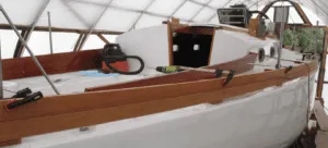
Satisfied, I ordered ¼-inch silicon bronze flat sheet from Atlas Metal. I built templates for each part of the bracket and my best friend cut them out on his metal-cutting bandsaw, then welded them up with his TIG welder. I determined where to position them and installed and bedded them on angled teak blocks with butyl rubber, G10 backing plates, and bronze bolts. Then I milled 7/8-inch thick mahogany, scarfing four pieces together per side that fit together via tongue and groove. I bolted them to the brackets one inch above deck with bronze bolts. I topped the whole thing with a teak cap scarfed together from the original beat-up teak cockpit coaming.
The top of the bulwark is 6 ¾-inches above the deck including the 1-inch gap. I painted the bulwarks blue and the cap white to reduce maintenance and provide a contrast to the white hull and cabin top. With the bottom of bulwarks an inch above deck any water on deck runs over the side without obstruction. There is no way for water to get into the boat at the gunwale.
THE DECK LAYOUT
I wanted a simple uncluttered deck layout that supported easy unrestricted movement around the entire deck. I terminated all the halyards and reefing lines on the mast on a pair of custom fabricated anodized aluminum belaying pin racks bolted to the mast and fitted with ironwood belaying pins.
We eliminated the Cape Dory stayail boom as I felt it provided limited value and could be a danger when working on the foredeck offshore. We had worked hard to fill in all the holes on the gunwale and I did not want to install a dedicated track for either the genoa or the staysail which just meant more holes in the deck.
Instead, we designed the bulwark to also serve as the anchor point for the jib leads via a nylon strop with snatch block which provided infinite adjustment. For the stayail, I installed a fixed bell-shaped bronze deck lead which gave the staysail about 3-5 degrees narrower sheeting angle than the jib.
Adjustments to the staysail are made by lengthening or shortening a pendant on the tack of the staysail. To tighten the leach, lengthen the pendant. To open it, make it shorter. Simple.
I located the primary and secondary winches so the handles would remain clear of the stanchions and within easy reach of the tiller.
STEERING
I converted the boat from wheel steering to tiller, freeing up the cockpit in the process. A tiller is simple and far more reliable than a wheel system. It reduces control line friction when using a self-steering windvane. A tiller also provides an easy-to-interpret language the boat uses to communicate with the skipper about sail trim and helm balance.
THE TRAVELER
I spent a lot of time thinking about the traveler. I did not want to retain the original mid-boom sheeting using a traveler forward of the companionway because it interferes with hard dinghy storage on the cabin top, puts great stress on the boom, requires hardware to be mounted on the cabin deck, and requires the use of a winch to trim the mainsail. Out of reach from the helm, a cabin-mounted winch is a slow way to trim a long mainsheet.
I originally wanted end-boom sheeting because it creates the least stress on the boom and would be out of my way in the cockpit. However, I could not make the geometry work. The best solution was a major compromise. We installed the traveler on the bridge-deck at the forward end of the cockpit.
It would at times be in the way of the companionway hatch and interfere with a cockpit awning, but there are advantages. It leaves the cabin top open for the storing of the dinghy. It provides very effective control of mainsail shape. It imparts minimal stress on the boom.
I incorporated a superb Antal 6:1 mainsheet block with integral jam cleat system, eliminating the need for a mainsheet winch. The mainsheet is completely accessible to the skipper. Straddling the tiller I can easily reach the jib, staysail, and mainsheet winches making tacking and gybing a singlehander’s dream.
BOOM GALLOWS
A boom gallows secures the boom when not sailing and when the mainsail is struck offshore. I have sailed many miles in rough conditions with just the staysail, and having the boom securely lashed down in the gallows prevents it from becoming a weapon. It took a while to figure out where to locate it as each location was a compromise. Ultimately, I installed it forward of the cockpit on the after end of the cabin top. I purchased the components from Port Townsend Foundry. Though I wanted teak for the support it was out of my budget. Instead, I used affordable Iroko and left it bare.
COAMINGS
I built new cockpit coamings from 7/8” thick African mahogany. I finished them bright but trimmed the tops with bare teak. I reused the original damaged teak coamings, ripping them into lengths I scarfed them together and incorporated them into the cap rails used on the new coamings and on the bulwarks. Teak is rot resistant and because it’s not varnished it absorbs abuse varnished wood could never withstand.
PRAM HOOD
We did not want a full width dodger because it would obstruct our view of the deck and sails and hinder moving forward out of the cockpit. Instead of a dodger, we chose to install a smaller pram-hood over the companionway hatch that protects the interior from rain and spray when the hatch is open. Our first one cost us about $175 and worked very well for two voyages. It was made from flexible irrigation pipe, bits of bronze offcuts, and waterproof Stamoid fabric. I replaced it last year with one slightly taller with windows and a strong stainless steel frame (see “Solving the Dodger Dilemma,” PS October 2022).
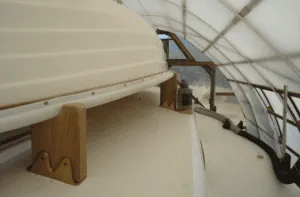
DINGHY STORAGE
When possible, the best place for a dinghy is inverted on the cabin top aft of the mast where there is no negative effect on trim and it is clear of the foredeck. Aft of the mast, it covers the saloon hatch which we can keep open in the rain or when sailing offshore. It is simple to launch and retrieve using the main halyard. PTF cast the bronze chocks. I did not through-bolt them. Instead, I dug out the core where the bolts penetrated the deck and epoxied in ½” thick G10 plugs. Then I drilled and tapped the G10 for 5/16” bronze bolts. The chocks are made to accommodate teak risers that hold the inverted dinghy’s gunwale. If the dinghy chocks are through bolted and the boat is ever swept by a wave the force could rip holes in the deck. So, it’s intended to be a break-away design. I built a set of square loomed ash oars which have been superb.
This completes Part III of this series. Next month I will describe the various systems we designed and installed on the Far Reach.
CONTACTS
ATLAS METAL,
Silicone bronze sheet metal
ANTAL,
mainsheet hardware
MCMASTER CARR,
SS fasteners, abrasives
JAMESTOWN DISTRIBUTORS ,
Assorted supplies, biaxial cloth
DEFENDER,
Assorted supplies
ELISHA WEBB,
Rigging supplies
MYSTIC RIVER FOUNDRY,
Custom bronze casting
AWLGRIP,
STAMOID
Dodger material
WORLD TIMBER ,
Mahogany, iroko, ash, exotic woods
IMPULSE TRADING,
Teak and ash
WORLD TIMBER ,
Mahogany, iroko, ash, exotic woods
WWW.SPARTANMARINE.COM,
Bronze hardware
PORT TOWNSEND FOUNDRY,
Custom bronze casting
DOYLE SAILS,
Sailmaker
I have long believed in the advantages of hand spliced 7×7 wire rigging. There are no hard spots so it does not work-harden at the swage or compression fitting like 1×19. The 7×7 wire has slightly more stretch and lower breaking strength than 1×19, so I increased the diameter by 1/32” to 5/16” and incorporated continuous intermediate upper shrouds reducing the load on the cap shroud by 40 percent.
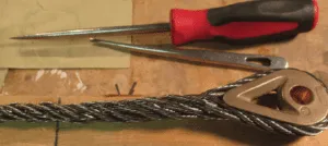
Stainless steel 7×7 does not need to be wormed, parceled, or served. I practiced making splices in the evenings with cheap 7×19 galvanized wire following the instructions in the late Brion Toss’ book The Rigger’s Apprentice. It took a few tries, but I figured out the basics. I then bought a roll of 316 SS 7×7 5/16” wire made in Europe and 24 bronze Merriman thimbles and went to work.
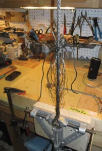
I contacted Brion Toss who was very encouraging. He told me to make a splice every day and email a picture of it to him. Then he emailed back a critique. From my first crude splices till I started splicing the actual rig it took me about 30 splices to get it nailed down but at the end Brion told me “You’ve mastered it.” When we hauled the boat to the boatyard I spent a couple weeks getting the boat ready. We assembled the mast, stepped it, and secured it with halyards. I had already spliced one end of the wires in the shop and cut them adding enough for the splice plus a foot more than I thought I needed. At the boat yard I climbed the mast and secured the upper end of the wire in the tangs and climbed down and marked the lower end. I climbed back up and retrieved the wires and took them home to the shop and spliced the other end. I went back to the boat and installed them. They fit perfectly. The wire and thimbles cost us about $1200. It saved us a small fortune.

I decided to install a dedicated trysail for the Far Reach for several reasons. First, we installed a taller mast which supports a larger than stock mainsail. I also wanted as big a working staysail as possible and the sailmaker had to ensure the double reef mainsail was the right size to balance the helm against the staysail. So a double-reefed mainsail on the Far Reach put up more sail area than on a stock boat. A trysail was a good option for providing us with a smaller sail better suited for heaving-to. Heaving-to is an important survival technique sure, but it’s also useful for holding station in more benign conditions such as waiting for a tide change or waiting for the sun to rise before entering an unfamiliar port.
Some may argue, and rightly so, that a triple reefed main is easier and quicker to configure than hauling up a trysail. But, a triple reef can be very hard on sail-shape unless the sail is made of very heavy fabric and then it is more difficult to handle for everyday sailing and flaking etc. But, the overriding factor for me was in rough conditions I wanted the boom lashed down in the gallows frame so it can’t become a weapon against the crew. Booms are killers. My trysail is designed to be flown without the boom. The clew incorporates two sheets, each one is lead to a cleat, or block, on the corresponding stern quarter of the Far Reach and then to a sheet winch.
Another consideration when planning for a trysail is the decision to use either a separate dedicated track or incorporate a mast gate to allow the trysail to be hoisted in the mast luff groove. I wanted a dedicated track as it meant one less thing to deal with on a dark windy night. Also, by having a separate track I can keep the trysail bent on its track and bagged on deck ready to go.
Different boat designs have different trysail requirements. In basic terms, fin keel boats tend to require trysails with a longer luff and shorter foot while long keeled boats like the Far Reach require shorter luff and a longer foot. So, before you make decisions about a trysail and the supporting track it’s important to discuss all these things with a knowledgeable sailmaker. Many sailmakers today have little experience with more traditional hull designs, so do your homework and pick the right sailmaker. Lin and Larry Pardey’s excellent book Storm Tactics covers the topic in detail.
I discussed these considerations with our sailmaker. He designed our trysail and provided me the specs for the sail before we built the mast. With that info in hand I was able to determine the length of the trysail track and where it needed to be positioned on the mast.
Because the tack of a trysail is usually positioned several feet above the goose-neck, it is usually secured with a pendant to a fitting on the mast or the deck. So, calculations for max hoist need to be made carefully. But to ensure there would be no problems I added two extra feet to our track length. The sailmaker advised me a 7/8” wide track was the appropriate size for our boat.
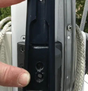
I installed the trysail track on our mast when we assembled our spar. An important step in the track installation was to incorporate a ramp which allowed the track to be installed just above deck level and pass over the boom gooseneck flange. We milled the ramp from composite deck board. But, I have seen it done with teak which seems a good choice to me.
Once I had the ramp built, it was a simple matter to lay out the track. I installed a short length of track over the ramp with machine screws so I could remove it and replace the ramp if ever necessary. The remainder of the track I installed with commercial strength SS pop rivets which require a large manually operated pop rivet gun. I drilled the holes as I went and lubricated the pop rivets with Tef-gel before I installed them.
At the very top of the track I installed a pan head machine screw under several washers that stood proud of the track as a “sail-stop” so the headsail slug can’t be hoisted off the top of the track. With the sail bent on the track and resting on the deck I also installed a locking car at the bottom of the track so the slugs can’t fall off the bottom of the track when bagged. My wife sewed a sail-bag about 8’ long which requires the trysail to be folded over itself only one time. The bag is run aft from the base of the mast and strapped to the hull of our inverted dinghy positioned on the cabin top aft of the mast.
To hoist the trysail I simply slide the bagged sail up the track and then lay it out between the lazy jacks on top of the flaked mainsail. The mainsail and boom are lashed into the boom gallows. Then, I pull the bag aft and off the trysail like a sock. Next, I run the sheets aft to the blocks and then to the winches and we are ready to hoist the sail between the lazy jacks.
I have not flown the trysail in anger yet. Before each voyage, I run the trysail up while we are anchored to make sure I remain familiar with the steps. I am looking forward to employing it, since I think it will work very well for us.
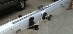
I was familiar with the Tides Marine Strong Track having read about it. But I had no plans to incorporate one. I thought it was an unnecessary expense. However, my sailmaker and spar engineer Robert Quates, who designed and fabricated our spar, were both adamant that I incorporate it into our rig. Their argument was it was crucial on an engineless boat to be able to get the mainsail up or down without drama. That made a lot of sense to me.
Installing the track was simple to accomplish with two people. Contact Tides Marine and they will send you sample sections to hoist in your luff groove before ordering the track. This step is essential to ensure you order the correct track. Our track came with three types of SS slugs: One for the sail headboard, one for the batten receptacles, and one to be installed opposite the reefs. Our mainsail has four full battens. Our sailmaker provided the batten receptacles pre-installed on the sail. Typically, Tides Marine supplies these and their installation is covered in the instructions.
We installed the track with the mast up in accordance with the instructions, which were clear and more than adequate. We kept the track coiled and with the boom removed from the gooseneck simply slid the track up the luff groove rotating the coiled track as we went. With the track run up the groove to the top of the mast, we measured the extra length at the bottom, and pulled it back down coiling as we went. We transferred the measurement of the extra length to the top of the track and cut it off with a hack saw to ensure there was about 1-2 inches between the masthead and the top of the track. We then ran the track back up the groove and installed the end plate and a single machine screw into the bottom of the track right above the gooseneck and tapped the screw into the mast.
In a single word the performance of the Strong Track can be described as “stunning.” The track is super slick. Letting go the main halyard the sail comes down like a cannon ball. I have raised, lowered, and reefed the mainsail on just about every point of sail without difficulty.


Regarding the Tides Marine track: I had one installed on my 36 ft sloop in 2010 and it performed very well including during a cruise in Mexican waters, and two round trips between California and Hawaii. I had no problem downwind reefing, which was a main goal for having the track. When I let the halyard loose, the main dropped like a rock. When the track was installed, I secured it to the mast to prevent movement using ~6 inch long Sikaflex beads about every 3 or 4 ft. In early 2022 I had the mast down and standing rig replaced. The Sikaflex had held, but the 12-yr old Tides track was trash; it cracked badly in places as I pulled it off the mast, and it was not hard to break it apart with my hands. I shuddered to think what might have happened if the track had failed and the main luff had come off while sailing. A sample of the track was sent to Tides and they said it was UV damage and it needed to be replaced, which I did. Tides Marine thinks it’s normal and expected to replace their track after about 10 years. I don’t see that caveat in their literature. Here’re some images of the old track: https://photos.app.goo.gl/VmTE6yiHsdrW3zr19