The lightweight anchor
THE LIGHTWEIGHT ANCHOR
All anchors are a compromise. Since some anchor types work best in certain bottoms, it is a good idea to carry anchors of different designs. At minimum, a cruising sailboat should carry at least two anchors adequately sized to anchor the boat under most conditions. Four anchors is often the norm on offshore cruising boats-two working anchors (a primary and secondary), one stern anchor or kedge, and one over-sized storm anchor-but cruising boats that sail with six or more full-sized anchors are not uncommon.
So where does a lightweight alloy anchor fit in the hierarchy of cruising anchors? It depends. Aluminum alloy anchors, particularly multi-part anchors, have a number of strikes against them. Lighter anchors take longer to set and are more likely to drag; their shanks are more vulnerable in side-load situations (aluminum alloys can shear when steel will bend); and multi-part anchors like the Fortress and Spade introduce other handicaps.
Despite these drawbacks, if Wednesday evening buoy racing is your passion, theres nothing wrong with an alloy race-day anchor. Owners of heavy-displacement boats with formidable bow rollers should look at high-tensile steel anchors for their primary anchor.
While high-tensile steel is the king of primary anchors, lightweight alloy anchors have two chief advantages-even for cruising sailors. They are portable, and they are easier to deploy by hand from a small boat. This is useful for kedging a boat into deeper water or away from a pier or obstruction.
Because alloy anchors are so easily moved around the boat, they don't need to be stowed on a dedicated bow roller, making them an appealing choice for a third, backup anchor- especially on boats with only one bow roller. Sizing an alloy anchor varies according to its purpose. Generally, the alloy anchor you choose should have similar holding capacity as the boats primary anchor.
For more advice and information on anchoring, purchase the ebook Specialty Anchors/Real World Anchoring from Practical Sailor.
Choosing an Anchor With the Appropriate Holding Power
Physical measurements of anchors cannot produce definitive conclusions about anchor performance, but they offer clues to likely performance in different conditions.
Our analysis found that the measurements (tip weight, total weight, blade area, etc.) of the tested anchors suggest that the Rocna and Manson Supreme should provide similar holding power when fully buried in a good bottom.
The Ray could have an edge in setting performance and in holding power in a common type of poor bottom (thin sand over rock/coral). One note of caution is that these measurements apply only to these particular size anchors, and scale effects may change the rank order in smaller anchors.
An anchors tip weight is the percent of the anchors total weight that the tip of the anchor puts on the sea bottom when the anchor is lying on its side. (The position the anchor normally assumes when it lands on the bottom.) This is viewed as an important factor in determining an anchors setting ability. The Ray has the heaviest tip weight of the three anchors tested.
Blade area is the surface area of the anchor blade when the anchor is completely dug in. This is considered an important factor in determining an anchors holding power. The Rocna has the largest total blade area of those anchors tested.
Tip blade area is the surface area of the first 9 inches of the blade tip. A common poor-holding bottom type has a couple inches of sand or mud over a harder rock or coral surface. According to Starzinger and Leonard, its been their experience that only the first 9 inches or so of the tip will bury in these bottoms-and often only two of the three flukes in a Bruce design-so this measurement is an indication of holding power in this sort of poor anchoring bottom. Of those tested, the Ray has the largest blade area.
For more advice and information on anchoring plus our evaluations of the anchors mentioned above, purchase the ebook Specialty Anchors/Real World Anchoring from Practical Sailor.
Hurricane Season: A season for planning
Tis the Season for Planning
The arrival of hurricane season is always a good reminder for boat owners to put together a storm plan detailing where and how the boat will be secured should a storm roll through.
Chafe protection for docking and mooring lines is essential for securing a boat ahead of a storm, but boat owners should also be sure to inspect the cleats themselves. The cleats should be beefy enough to handle the task at hand, and they should be properly supported with sturdy, easy-to-inspect backing plates. In addition to ensuring your cleats are structurally sound, its also important to pay attention to line leads. If a line must make a sharp bend at a chock or cleat, the risk of chafe increases significantly, and attaching anti-chafe gear at the bend is imperative.
Also, if your boat will be riding the storm out on a mooring, be sure to inspect the chain, swivels, and pendant on that mooring for wear. At the heart of any storm prep plan that involves anchoring is the ground tackle and how its set. PS Technical Editor Ralph Naranjo has used the following anchor combination and anchoring system with success in various locations to moor his 41-foot Ericson sloop:
A 45-pound CQR, with 10-millimeter (3/8-inch) all-chain rode, 5/8-inch nylon snubber, and leather anti-chafe gear.
A Paul Luke 75-pound, three- piece fisherman storm anchor, 50-feet of 1⁄2-inch chain, 200-feet of 3⁄4-inch nylon, leather anti-chafe gear (no swivel).
Set the two anchors at about a 60- degree angle, placing the storm anchor toward the worst of the expected wind and sea. Leave enough swinging room to cope with the likely wind shift, which could be as much as 180 degrees.
For more advice on protecting your boat and anchoring gear, purchase the ebook Anchor Rode Accessories from Practical Sailor.
Helping Your Boat Battery Survive Winter Storage
Page 22
Helping Your Boat Battery Survive Winter Storage
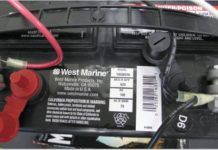
Few things are more disappointing than coming back to your boat in the spring and discovering that one or more of your boats batteries is dead. You havent even started sailing, and already youre facing a hefty bill. Many times, a dead battery can be resuscitated to near its initial capacity, but its best to avoid the problem in the first place.
If you put your boat to bed recently and havent yet checked your batteries state of charge, now is a good time to do it. Ideally, you should bring a stored battery up to full charge at least once a month. So long as you keep your batteries fully charged, you shouldnt have to worry about electrolyte freezing. A fully charged, lead-acid battery will withstand temperatures of 75 degrees below zero without freezing. However, electrolyte in a discharged battery will start freezing at 32 degrees, just like water. Once the electrolyte freezes, you can pretty much kiss your battery goodbye.
If you havent put much thought into storing your battery for the winter yet, don't delay any longer. The batteries should be removed from the boat and stored in a cool place that does not drop too far below freezing. A basement or garage is fine. Todays batteries can be safely stored on a concrete floor without risk of discharge, but its a good idea to insulate them on a block of wood anyway-if only for peace of mind. You can keep house batteries on the boat, but if you do, you should take the usual winterizing steps-cleaning the battery top and battery posts, filling the electrolyte, eliminating any loads that may discharge the battery-and checking voltage and recharging on a monthly basis.
There are a few ways to check battery state. The more com- mon methods of checking battery state are using a digital or expanded-scale voltage meter to check open-circuit voltage or, on wet-cell batteries, using a hydrometer to check the electrolytes specific gravity. In either case, you need to make sure the batterys electrolyte is stabilized, otherwise you may get misleading results. By letting a battery rest for an hour or two after recharging-or after being subjected to discharge loads-the electrolyte is usually fairly stable. Typically, the electrolyte will be stabilized after only a few hours (or even minutes) of rest, but in some cases it may take up to 24 hours, even longer in some gel batteries.
If you have serious concerns about your batterys condition, you should consider having it load-tested at a reliable battery service center. Big boatyards, most automotive repair shops, and battery dealers will have a heavy-duty load tester suitable for high-capacity marine 12-volt batteries. Owners of inboard diesel engines can simulate a load test, a process that is described in Nigel Calders Boatowners Mechanical and Electrical Manual. Calder also describes how to compensate for temperature when checking for battery state and offers a few options for reviving bad batteries back to near capacity, tricks that can save you hundreds of dollars that you might have spent on a new battery you didnt need.
For more information on marine batteries and other electrical systems, purchase Marine Electrical Systems, Volume 1, Batteries from Practical Sailor.
Or, buy the entire Marine Electrical Systems five-part series!
Zincs and Protection From Galvanic Corrosion
Page 4
ZINCS AND PROTECTION FROM GALVANIC CORROSION
Use zincs to protect against the galvanic currents that are set up by dissimilar metals on your boat that are immersed and that are in electrical contact with one another. The best example is your bronze propeller on a stainless steel shaft. The best protection is to put a zinc right on the shaft next to the propeller, or a zinc on the propeller nut. An isolated bronze through-hull doesn't need protection because it is not in electrical contact with another immersed dissimilar metal. If electrically isolated, high quality marine bronze is electrochemically stable in seawater; nothing good can come from connecting wires to it.
Stainless steel is a special case. Generally, it is a bad idea to use stainless steel underwater, because it can pit. When it pits, the nobility of the metal changes locally, and you end up with tiny galvanic couples that are made up of different parts of the same piece of metal, and the pits grow deeper. One school of thought suggests that if you must use stainless steel underwater (e.g. you need its strength), then you should connect a nearby immersed zinc to it; this protects the stainless steel from itself, reducing the rate of pitting. The electrochemistry of this assertion is compel- ling enough that you ought to protect a stainless steel rudder shaft with a zinc. This may be done by mounting a zinc on the hull near the rudder shaft, and electrically connecting it (inside the hull) to the stainless rudder shaft. For the reasons described above, ensure that your metal rudder shaft is not electrically connected to anything else. Your stainless steel propeller shaft will be protected from itself by the same shaft zinc that protects the propeller from the stainless steel shaft. In both cases, the pits, if they appear, will appear where the stainless steel is not exposed to the water. Trouble areas are in the cutless bearing, inside the rudder bearing, and just inside the top of the rudder.
Keep your metal keel/ballast electrically isolated from all other bits of metal. If you have the misfortune to have an external iron or steel keel, however, mount a zinc directly on it to reduce the rate of corrosion.
For more information on installation of marine electrical systems, purchase Marine Electrical Systems, Volume 2, System Installation from Practical Sailor.
Or, buy the entire Marine Electrical Systems five-part series!
Stepping up to 24 VDC
Page 4
Stepping up to 24 V DC
Weve been witnessing an increasing trend of new boats in the 40- to 60-foot range being manufactured with dual-voltage electrical systems (12 VDC and 24 VDC). So we called the electrical engineering departments at a few high-end boat manufacturers to find out about the driving force behind outfitting vessels with 24VDC electrical systems.
The boatbuilders told us that the 12VDC electrical loads on new custom and semi-custom boats over 40-foot boats are staggering. Electric windlasses, electric bow thrusters, electric winches, underwater hull lights, and DC power inverters-these are just some of the must-haves on todays pocket yachts. Unfortunately for the electrical engineers who are designing the distribution systems for these new niche vessels, most of the high-amperage loads are located at opposite ends of the vessel, far away from the vessels battery banks.
Although most high-amperage accessories operate for only brief periods of time (bow thruster, windlass), they still require upwards of several hundred amps when operated at 12VDC. Because the cable runs to a bow thruster (high amperage load) are typically long, and we are only starting out with 12 volts, very large diameter power cables are required to keep the voltage to the thruster from dropping more than 10% when the thruster is under load.
Large-diameter cables mean more copper, and more copper means more weight. The last thing a boatbuilder wants to do after having gone through all the expense of using E-glass balsa-cored composite materials or carbon fiber to make their boat lighter, faster and more efficient is to have their own electrical department load down the boat with hundreds of feet of heavy cooper wire. The solution is to increase DC system voltage, which reduces the amperage requirements of the DC accessories. With amperage requirements lessened, smaller diameter (lighter) power cable can be installed. This in turn will help the vessel hit its performance numbers.
This sounds like a lot of trouble to save a couple of hundred pounds of weight on a 40-foot vessel, but when you move up into the 60-to 80-foot range, the weight saving averages around 35 to 40 percent.
For more information on marine batteries and other electrical systems, purchase Marine Electrical Systems, Volume 3, Panels, Monitors, Charging from Practical Sailor.
Or, buy the entire Marine Electrical Systems five-part series!
Breaker Panel Installations – DIY Tips From the Pros
Page 7
DIY Installation Tips From the Pros
We made some calls to a few well-respected boat yards and asked their electricians what problems they have experienced with customer-installed (DIY) breaker panel installations.
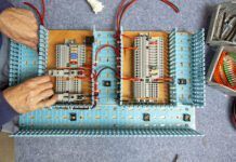
Almost all of the electricians said that there is usually not enough wire length left behind the panel to comfort- ably (and safely) remove the panel for service. Another problem: The accessory panels are being installed in spaces that do not have sufficient depth to accommodate the panel and the radius of the primary feeder wire. The pros indicated that this squashing usually loosens the feeder attachment point and causes all sorts of intermit- tent voltage problems.
We were reminded of the importance to mark and identify your wires before you remove the old distribution panel. Mark the individual accessory wire with a number, and if you can get your hands on the jacketing of the two core wire as it enters the electrical panel, print right on the wire with a fine point permanent marker the wires identification name (stern light, radar, etc.). A few of the electronics dealers we spoke with mark their distribution wires with a portable label-making machine, made specifically for marking wires. This wire-marking system prints out clear wire tags that wrap around the wire, much like a clear Band-aid.
Another area of concern is the soldering of crimp terminals onto the distribution wires. We were told about several DC panel installations that looked absolutely perfect at first glance. The wires were well marked, well organized into bundles, and stitched up with wire spiral wrap. The only problem was that all of the lug connections to the individual circuit breakers were soldered, but not crimped. Solder melts at a low temperature and therefore is convenient to work with on copper wires. But when wires heat up from overcurrent or an electrical short, the solder will melt and the electrical terminal will fail. (The approximate melting temperature of 60/40 solder is 360 degrees Fahr- enheit). Always crimp your terminal lugs. You can add solder to finish up a lug, but the physical crimp is how the lug was designed to be attached to the wire.
For more information on marine batteries and other electrical systems, purchase Marine Electrical Systems, Volume 3, Panels, Monitors, Charging from Practical Sailor.
Or, buy the entire Marine Electrical Systems five-part series!
Inverter-Charger Terminology – What Does All That Mumbo-Jumbo Mean Anyway?
Page 16
What Does All that Mumbo-Jumbo Mean Anyway?
Established industry standards enable consumers to know what exactly it is theyre buying. They set a benchmark for product quality, performance, and safety, allowing consumers a point of comparison. Compliance, certification or third-party testing are not required, but in the case of inverter-chargers, if a manufacturer can honestly claim that this has been done, it gives them a leg up on their competitors, in our opinion.
However, this is a tricky area, and rest assured, manufacturers play games with it. To help readers decipher the related alphabet soup, we offer this roundup of the terminology often used with inverter-chargers.
[pick up UL, ETL, CSA and CA logos from websites]
? UL: Underwriters laboratories. A nationally recognized, in- dependent, nonprofit organization that writes standards and tests products for safety certification. (www.ul.com, ulstandardsinfonet.ul.com/)
ETL: originally ETL Testing laboratories, now Intertek Testing Services. A nationally recognized third-party product safety test lab. (www.intertek.com)
ISO: International organization for Standardization. The worlds largest developer and publisher of international product standards, ISO is a network of standards groups in 163 countries. (www.iso.org)
CSA: Canadian Standards Association. A nationally recognized and fully accepted, nonprofit standards group on a par with the UL or ETL. (www.csa.ca)
CE: The CE mark is the makers declaration that the product conforms to all applicable European Union standards. Any manufacturer can self- certify its products to CE.
ABYC: American Boat and Yacht Council. Develops safety standards for the design, construction, equipage, maintenance, and repair of small craft and their systems. ABYC Standard A-31 relates to inverter-chargers. (www.abycinc.org)
Listed or Certified to: These words imply either third- party testing of equipment to ensure compliance with industry-recognized and accepted performance and safety standards, or in the case of European products a manufacturer declaration of conformity to some pretty strict ISO Standards. These products often carry the logo of the certifying group, like those shown here for UL, ETL, and CSA listed products.
Designed to comply with: This is nothing more than the makers good word that on the drawing board, things looked great, but there is no assurance that the product actually com- plies with industry standards.
For more information on marine batteries and other electrical systems, purchase Marine Electrical Systems, Volume 3, Panels, Monitors, Charging from Practical Sailor.
Or, buy the entire Marine Electrical Systems five-part series!
Wind Generators 101
Page 4
WIND GENERATOR 101
Wind turbines convert the kinetic energy of the wind into mechanical power, and ultimately electricity. This electricity can be used immediately to power equipment, but is typically stored in batteries for future use. Larger turbines may generate enough power to carry or float larger loads (such as a small fridge during an overnight stay aboard), while smaller units produce enough electricity to power smaller loads for a few minutes (bilge pumps, etc.) or perhaps top off your battery banks after a weekend outing.
All generators share a few basic components: a rotor-they don't propel, so theyre not propellers-with aerodynamic blades, an electrical generator, some form of rotor over-speed control, and a mounting system (pole, arch, etc.). Most also will have rotating electrical contacts, which enable the unit to operate in a continuous 360 degrees of rotation. All but one of the units in our test, the KISS, had this feature. The KISS generator has an internal spring (inside the mount) and a rope lanyard tied to the tail of the unit and mounting pole-the lanyard is a specific length to prevent the unit from rotating more than three or so times, after which the spring is supposed to return it to its original position once the wind dies down.
Wind turbines either produce direct current (DC) or alternating current (AC) power, which is then converted to DC via a rectifier. Of the models we tested, the KISS and both Ampair units utilize a rectifier to convert AC to DC, while the Rutland 913, Air Breeze, and Superwind 350 produce DC. Each approach has its pros and cons: AC can be transmitted over longer wire runs with less power loss (due to overall resistance of system wiring), even when smaller gauge wire is utilized. DC systems, on the other hand, don't require the use of a rectifier, which reduces expense, cuts down on the number of parts that might fail, and eliminates a few installation steps. As for cons, DC motors have brushes and commutators, both of which require periodic maintenance to prevent generation of electromagnetic interference (EMI), which can disrupt onboard electronics. The rectifying diodes in AC-producing units can also be damaged if exposed to reverse-polarity voltages during installation or maintenance.
For more information on wind power generation, purchase Marine Electrical Systems, Volume 4, Alternative Energy.
Or, buy the entire Marine Electrical Systems five-part series!
Choosing Solar Panels for Your Boat
Page 17
SOLAR POWER
In simple terms, and leaving out the quantum nature of light, solar panels work by converting the energy in sunlight (or any light) to an electric current. The sunlight striking the silicon material in the panel causes the material to give up electrons, which then can be used to power something, or for storage in a battery. The amount of power potentially available from the panel is related to the light intensity, the angle of the light to the panel, the panels temperature, and the cell material.
LIGHT INTENSITY. The greater the amount of light falling on the panel, the more power available from the panel. The output of a panel is comprised of two measurable quantities, voltage and current. While solar panel voltages are fairly insensitive to light levels, the output current will double for each doubling of the light intensity. Since power is the product of voltage times current (P = V x I), and since the voltage is pretty constant, the power output is directly proportional to the current. Monitoring the current will be a close analog of the panels output power.
ANGLE. The angle of the solar panel to the sun will have a fairly large impact on the panels power output. For the best results, the light should hit the panel perpendicularly to its surface. As the suns angle moves away from perpendicular, the light intensity falls off as the cosine of the angle. One simple way to demonstrate this effect is with a pad of paper and a desk lamp. Hold the pad so that its surface is perpendicular to the light and then notice the size of the pads shadow. Now, change the pads angle away from perpendicular and watch the effect on the
shadow. At increasing angles, the shadow will get smaller. The smaller the shadow, the less light hitting the pad (solar panel). Additionally, below a certain angle, the sunlight will just reflect off the panels surface without producing electricity.
TEMPERATURE. The silicon material used in the production of the solar panels is sensitive to variations in temperature. As the panel temperature increases, the power output goes down. As a rule of thumb, the power output goes down 0.5%/C (or about 1%/F). The panels, since they are absorbing solar energy, will be warmer than the surrounding air. Therefore, air temperature will not be a good indicator of panel temperature. Also, some panel ratings are given at 20C (68F). Hence, on a warm summer day of 90F, and ignoring the increase in the panels temperature due to solar absorption, the output power will be about 20% less than the rated power.
CELL MATERIAL. Solar panels fall into three distinct groupings: monocrystalline, polycrystalline, and amorphous.
For more information on Solar Power, as well as readers real-world experiences with panels from various manufacturers, purchase Marine Electrical Systems, Volume 4, Alternative Energy.
Or, buy the entire Marine Electrical Systems five-part series!


