

Any sailor who has tried to wrestle a full-keel ketch with a barn-door rudder into a tight slip has probably wondered if they could modify the rudder to improve low-speed maneuvering without slowing the boat down under sail. As it turns out, there are several rudder design tweaks designed to improve control on ships, large working boats, and trawlers, but few have been implemented widely in the sailing world.
Most sailors have a general understanding of how a rudder works, because the concepts of lift and drag that apply to sail trim and keels also apply to what happens underwater with respect to rudder trim. The rudder’s angle in relation to the flow of water as the boat moves through the water is its angle of attack. When this angle changes, it creates a low-pressure zone on one side of the rudder that “lifts” the rudder forward toward that zone. On the other side of the rudder is drag, the enemy of lift.
At low speed, or when making sharp turns—two essential features of any docking exercise—the lift is so anemic that drag can cause the rudder to stall, and the skipper must rely on other forces such as prop walk (forces generated by the propeller’s rotation) or prop wash to squeeze the boat into its slip. For responsive steering when docking, you want a rudder profile that has a healthy lift-to-drag ratio at low speed. This is not possible using the most popular rudder designs, which are based on foils developed by the National Advisory Committee for Aeronautics (NACA). The NACA foil shapes, designed to provide optimal lift-drag ratios for aircraft operating at higher speeds when flying a relatively straight line, are not the best suited to making sharp turns at slow speeds.
Reader In Need
Our dive into the world of rudder designs for low-speed maneuvering was triggered by questions from a reader who was frustrated with the close quarter maneuvering capabilities of his full-keel sailboat. He was happy with the boat’s performance when sailing, but under power, and particularly at low speed, the boat simply would not turn. He had read that if he attached a 90-degree angle iron on each side of his rudder’s trailing edge, his rudder would be far more effective.
Since a modification that adds drag at the trailing edge seems to go against the conventional wisdom that a knife-like trailing edge is best for sailboats (see “Building a Faster Rudder”), he was baffled to say the least. We were curious, too. Are there unconventional rudder profiles—at least in the world of sailing—that might be a better fit for a boat like his? When docking in close quarters, an auxiliary-powered sailboat effectively behaves as a powerboat, so it is worth looking at what rudder modifications have helped trawlers, fishing boats, or commercial ships tighten their turning radius.
Sailboat Rudders
Sailboat rudders serve as both a control device for steering and lateral plane to develop lift. When sailing straight, or nearly so, the rudder operates at a relatively steady, low angle of attack. The low angle is nowhere near one that would interrupt the flow of water and cause the rudder to stall.
On a well-designed sailboat in good trim, weather helm is about 2-5 degrees. This is the rudder angle required to steer a straight course while reaching. But that’s just part of the equation. Like the keel, the rudder is impacted by leeway, slipping about 5 to 10 degrees in relation to the course steered. This means the rudder’s actual angle of attack through the water is about 7 to 15 degrees.
An efficient NACA rudder profile will provide a favorable lift-to-drag ratio up to an angle of attack of about 16 to 20 degrees, so you have limited “wiggle-room” before the rudder will begin to stall.
Surface Area and Aspect Ratio
Because a sailboat rudder needs to provide lift at relatively low speeds, it needs a relatively large surface area and a foil shape with a high aspect ratio. Aspect ratio is the ratio between the chord—the straight-line distance between the leading and trailing edges of the foil—and the foil’s span, or length (depth in the case of a sailboat rudder).
These narrow and deep NACA-based rudder shapes are designed for maximum efficiency going to windward. They provide adequate maneuverability under sail but aren’t very efficient under power. Racing designs exacerbate low-speed steering problems by putting the rudder as far from the prop as possible to minimize turbulence at the rudder. This makes it virtually impossible to nudge the stern to port or starboard by redirecting propwash with a sharply turned rudder a common tactic during docking maneuvers.
Powerboat Rudders
The rudder on an inboard-powered trawler or cabin-cruiser by comparison, operates in the high velocity slipstream of the propeller. It is not asked to resist the steady sideways pressure of the wind, only to provide turning force. Any additional rudder area hanging below the prop’s stream only adds drag (and draft) with very little benefit. The profile must be low drag, and as a result, many powerboat rudders are nothing more than a flat plate welded to a shaft with whatever reinforcement is required. This provides acceptable docking performance so long as the timely bursts of power are applied at the right rudder angle. Larger ships, with a lower power-to-mass ratio, require some additional help.
Ship Rudders
Ocean going ships focus on straight-line efficiency. They are assisted by a harbor tug when docking. They use rudder sections like those of sailboats for slightly improved lift-to-drag ratios, but the rudder remains small. However, some ships, including tugs, coastal freighters, and barges, require greater maneuverability. When navigating in constrained waterways, these ships and work boats spend a great deal of time with the helm turned at high angles.
As a result, naval architects have developed different rudder sections that will operate effectively at much higher angles than traditional NACA sections we see on sailboat rudders. These convex shapes are referred to as “fishtail sections”. Examples of fishtail rudder designs are the Schilling and Thistle rudders (proprietary foil sections named by their designers), which can reduce the turning circle of a boat by as much as 50 percent. Some examples of these low-speed designs are shown alongside conventional sailboat rudder (NACA) profiles in the illustration.
If you have a spade rudder located a few feet away from the prop, you won’t gain anything with a fishtail section. Effective use of prop-wash—along with an experienced hand at the helm—should be enough to get you in and out of a slip. However, if you are the owner of a shoal draft boat with a short rudder, a full-keel cruising boat, or a motorsailer, and have been kept awake by visions of bow thrusters dancing in your head, read on.
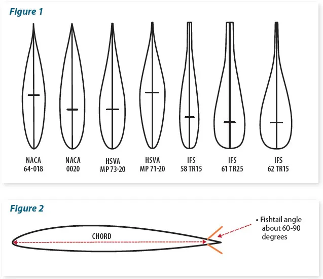
(IFS, Institute für Schiffbau). Figure 2: Adjustable metal flaps at the trailing edge (bottom) could help develop the ideal wedge angle.
Low Speed Steering Under Sail
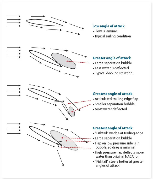
At low angles of attack, water flows relatively evenly around both sides of the rudder, creating minimum drag. This streamline, also called laminar flow, remains “attached” to the rudder’s surface. Any change in relative speed or direction that interrupts this flow can cause the rudder to stall.
When a rudder stalls, the water on the low-pressure side is no longer deflected effectively, creating a separation bubble that reduces lift on the low-pressure side. At the same time, drag on the high-pressure side of the rudder continues to rise. As result, the low-pressure side of the rudder’s trailing edge becomes less important, because it is within the eddy zone (separation bubble, see adjacent illustration). Since there is very little water flow over this surface, it does not create much drag. Only the flap on the high-pressure side sees flow and generates drag. We’ll come back to the latter point, but it should be apparent that sailboat rudders cannot operate in the stalled region; the drag is too high for windward work, and the lift is too low for high-speed corrections in big waves.
Low Speed Steering Under Power
When maneuvering under power at low speed we need more lift, so drag doesn’t really matter. To overcome any drag, we can just use more throttle. Airliners use massive flaps when landing. The drag is horrendous, but since they are descending and trying to reduce speed, they have plenty of reserve power to overcome drag. The tradeoff is worth it. During take-off, when they have less power to spare, they use zero flaps (and sometimes high-lift devices called slats on the wings’ leading edge).
In search of new symmetrical shapes with the same high lift characteristics as an asymmetrical airplane wing, ship designers began experimenting. In fact, some ships use rudders with flapped trailing edges, like airplane flaps, but simpler. After much trial and error, simpler, non-articulating sections, referred to as fishtails, were found to have many of the same beneficial characteristics as a jet wing.
As a result of this research, a series of foils were developed in Germany by the Hamburgische Schiffbau Versuchsanstal (Hamburg Model Ship Basin) and the Institute für Schiffbau (Institute for Ship Building). Named after their place of origin, these shapes were designated HSVA shapes and HVS shapes. A variety of proprietary wedges and fishtails grew from there.
When a vessel is steering a straight path and the rudder has a low angle of attack, HSVA and HVS shapes create slightly more drag than NACA profiles of equal lift. However, they delay stall and create more lift at higher angles. Although the wedge or flap slightly increases drag, once the foil stalls, this drag is minimized because it is in the separation bubble.
Fishtail Designs
As shown in the example foils (see Figure 1), the “fishtail” is a wedge-like section at the trailing edge. Generally, the maximum thickness of wedge will be no more than the maximum thickness of the rudder. The ideal thickness of a sailboat rudder is about 20 percent of the chord—the distance between the leading and trailing edge measured parallel to the normal laminar flow (see Figure 2). Ideally, a fishtail rudder will be based on a concave HSVA or HVS section, but simply adding a wedge at the trailing edge of NACA profile or a flat plate has proven to be a cost-effective way to achieve similar performance.
Adding End Plates
Another feature of high-lift rudders are endplates. Just as the name implies, these are plates at the top and bottom “ends” of the rudder. Their purpose is to help direct laminar flow over the rudder, by reducing loss of flow at the rudder tips (known as tip loss).
You don’t often see endplates on sailboat rudders or keels because they can create a lot of turbulence and drag. In addition, the deep, narrow (high-aspect) rudder of a sailboat will suffer much less tip loss than a broad shallow (low-aspect) one found on most powerboats. Finally, the narrow gap between the top of the rudder and the flat stern section of a racing sailboat effectively creates an endplate at the top of the rudder, eliminating the need for one there.
Endplates will be more appealing to owners of motorsailers, heavy-displacement sailboats with barn door rudders, or other large auxiliary sailboat designs that can create headaches during docking. On these boats, the additional drag under sail may be worth better maneuverability under power.
These “endplates” on a sailboat rudder don’t have to be at the ends of the rudder as they are on a powerboat; they can be at the top and bottom of the rudder’s prop wash zone to help direct laminar flow and improve rudder lift under power. On a motorsailer, to make full use of the prop thrust, the distance between the end plates should about 120 percent of the prop diameter. The plate width should be about 120 percent of the maximum thickness of the foil, or, in the case of a thin, flat rudder, 20 percent of the chord.
Other Considerations
Adding endplates or a fishtail can have some unintended consequences. For example, it will move the rudder’s center of effort aft, making it harder to steer. The change is most pronounced at low speeds with the helm well over, but forces are low, so this is not typically a problem. At higher speeds, the difference will be more noticeable, and this is something to look for during a sea-trial before you commit to a permanent change.
To get the maximum benefit of a fishtail rudder with or without endplates, one could also experiment with moving the end stops, which limit the maximum angle you can turn the rudder to either side—although we’d be very careful with this. Rudder end stops generally limit rudder angle to 35 degrees, the maximum angle at which conventional rudder designs are effective.
A fishtail design will work beyond this limit, up to 45 degrees, potentially reducing turning radius by up to 50 percent at speeds of 2 to 4 knots. However, increasing rudder angle will also increase loads on the rudder stock and rudder bearing when the boat is in reverse or, more seriously, getting tossed backward by a wave in extreme conditions. Although we have few qualms about experimenting with end plates and wedges, we wouldn’t mess with rudder stops on an offshore cruising boat without some professional guidance from an engineer or naval architect.
While this seems like a lot of effort to make docking easier, having control at low speed can be beneficial at sea, as well. You will have better control when powering in adverse weather, slowing down to the minimum speed that allows for control—steerage speed—which can help in heavy weather.
Conclusion
This report is not advocating for rudder redesign on a sailboat that steers adequately at low speeds under power. Nor should it be construed as surefire way to fix steering problems on problem boats, although we’re optimistic that it will help. Based on solid evidence from the world of trawlers, working boats and ships, it is a concept that deserves more study. We have not yet been able to test fishtail rudders on our own sailboats, but many vessels, both commercial and recreational—have added fishtails with positive results. We’d be interested in hearing from sailors who might have experimented with either.
Endplates
As for endplates, we strongly believe that they are smart idea on trawler rudders; the only downside is that it can snag weed. To prevent this, we would leave the forward portion of the plate flush with the leading edge of the rudder and then rake it in a streamlined form as it extends aft. Shallow-draft motorsailers with trawler-like rudders could also benefit from streamlined endplates. As mentioned, the endplates don’t have to be at the rudder tips, they could be positioned to maximize prop wash.
Fishtails
Adding a fishtail becomes more complicated. What angle works best? How will it impact rudder balance? The HVSA sections are a good starting point when conceptualizing fishtail sections. Although adding a simple 90-degree angle at the trailing edge is common, naval architect Dave Gerr, the author of several books on yacht design and engineering, suggests starting with a metal plate that can be adjusted to alter its angle.
Experimentation
If you want to experiment, you could attach a stainless-steel sheet metal strips to each side of the rudder. The metal would be bent at an angle that mimics the shape of your preferred fishtail. During sea trials, you can adjust the angle until you find one that works. If you are using stainless-steel bolts or screws to fasten the sheet metal, you will want to be extremely careful about not allowing any water into the rudder laminate or foam core. Seal the core with epoxy as you would when fastening deck hardware or fasten the angle using high-strength adhesive.
If the angle doesn’t seem to help, you can take it off, fill the holes, and master the art of using spring lines to squeeze your boat in and out of its slip on windy days. If your improvised fishtail does improve low-speed steering, consider shaping a more permanent section that can be bonded to the original rudder—or building a new rudder to the improved design. If you are also adding endplates, the fishtail sections do not need to be mechanically attached to the endplates, but they should be very close.
Bottom Line
Full keel sailboats are never going to turn on a dime; they like to go straight. But there is plenty of evidence that a fishtail section, such as the concave IFS61, located just aft of the prop, could improve low-speed performance. We doubt this fishtail section located directly behind a 3 to 4 blade fixed prop will have any negative effect on sailing—the flow is turbulent behind the prop anyway. As for the potential benefits, based on what we’ve seen in the powerboat world, a low-speed rudder design is worth investigating.
References:
SHIPS AND OFFSHORE STRUCTURES
Volume 12 (2017), Issue 4.
“Sixty Years of Research on Ship
Rudders: Effects of Design Choices on Rudder Performance,”
by Jialun Lee and Robert Hekkenberg.
www.tandfonline.com
GREAT HARBOUR TRAWLERS –
www.greatharbourtrawlers.com
MARINE TECHNICAL SOCIETY
2012 CONFERENCE.
“Station Keeping with High
Performance Rudders,”
by Joerg Mehldau
www.dynamic-positioning.com
OCEAN NAVIGATOR June/July 2005.
“High Lift Rudders and Improved Boat Handling,”
by Dave Gerr.
www.oceannavigator.com
PROFESSIONAL BOATBUILDER.
“Keel and Rudder Design,”
by David Vacanti.
www.ericwsponberg.com
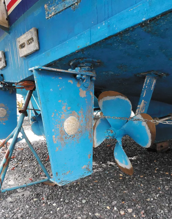
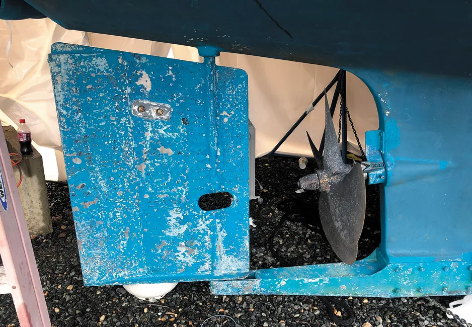
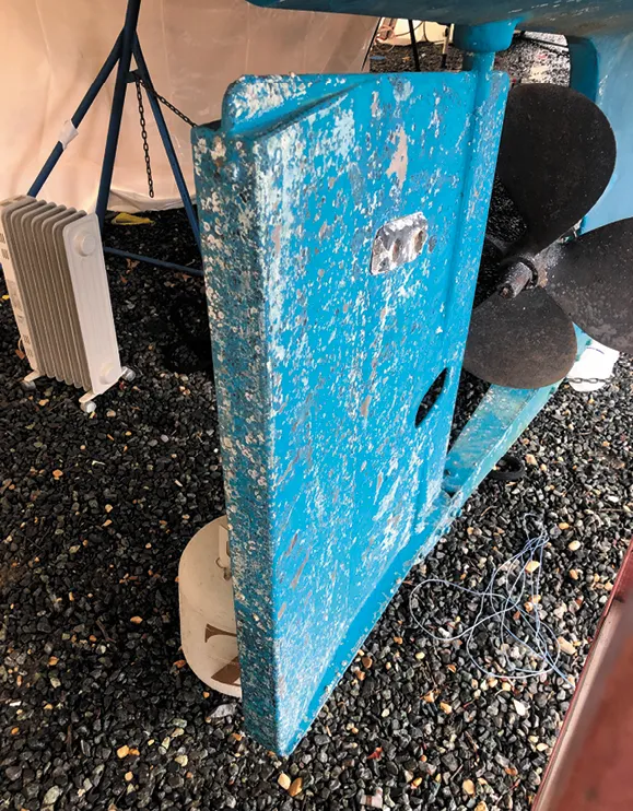
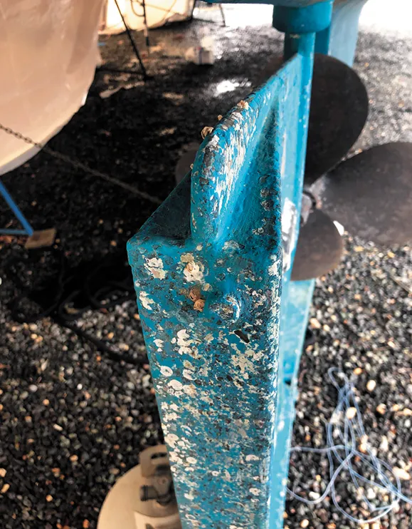
1. This Defever trawler rudder has end plates for better steering at low speeds. There is also a slight “fishtail” flare at the trailing edge.
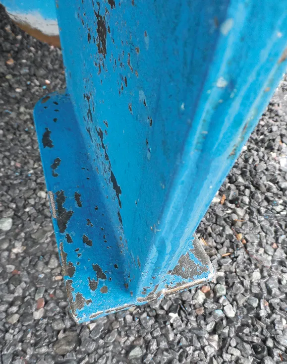
2. The flare consists of a triangular strip of 3⁄8 inch steel welded to each side. The endplates are flat stock welded to the end of the rudder.
3. Directly aft of a big four-blade prop, this fishtail wedge helps the boat achieve a tighter turning radius by improving lift at extreme rudder angles.
4. The wedge on this high-lift rudder on this 50-foot trawler is much more pronounced than the one on the Defever (images 1 and 2).

This article was originally published on 24 October 2023 and has been updated.


My boat is a Swallow Craft Swift 33. It had a “barn door” skeg hung rudder. it was a bear to steer and zero directional control in reverse. I’ve forgotten most of the math but basically I lengthened the rudder 11″ and extended the rudder forward of the pivot point. There was a fair amount of math involved (for me anyway). Now I had a hydrodynamic counterbalance forward was like power steering and some control in reverse. Great article, just adding my experience.
Foils don’t know if they travelling at high speed through air or low-speed through water. Water is almost a thousand times denser, so there can be a great deal of overlap in effective designs. Reynolds Number is what matters most to lift.
If you notice a substantial loss in control authority while docking, try using less rudder angle. If you crank any rudder past it’s stall angle, it will instantly lose most of it’s authority. If your rudder stops were set properly, this should not be possible, but it’s probably low on the list of considerations your designer had. If you’re rudder is stalled, reducing the steering angle should allow the flow to re-attach, improving effectiveness.
The 90 degree trailing edges you refer to are often referred to as Gurney flaps. They increase upstream pressure, thus delaying separation and allowing you to operate at a larger angle of attack. As you correctly pointed out, they will increase drag under low-angle of attack conditions, but there’s not much easier than tacking a small strip of angle stock to the trailing edge.
Endplates do not create drag, they lower it by reducing induced drag. The main reason not to use them is how effective they are at catching weeds and getting you stuck in the mud.