

A typical cruising boat has thousands of electrical connections. The consequence of failure range from a light that doesn’t work to a fire that can cost lives.
Connections must be physically strong to keep resistance low, and remain corrosion-free for a lifetime, enduring vibration and attack by heat and saltwater. It is commonly estimated that over 90 percent of electrical failures on boats result from poor connections. It is no wonder that marine electricians have high standards.
Crimp connectors are the gold standard. They occasionally get a bad name from shoddy crimps made using vice grips or discount store plier-style crimpers.
On the other hand, a properly adjusted ratchet crimper practically welds the fittings to the wires, and failures are scarce. We’ve made countless thousands of crimps over the years, including hundreds for Practical Sailor salt spray chamber testing, and we’ve never had a failure. Cheap buss bars have corroded away, but never one of our ratchet crimps. But we’re getting off the topic.
Some DIY sailors are addicted to soldering. The are firm in their opinion that no other connection can be as reliable and corrosion proof. This is true, to a point. We’ve done some testing of solder connections and they can be very good.
Nevertheless, the American Boat and Yacht Council (ABYC) recommends that solder not be the sole means of connection. The danger is that when overheated, the solder can melt and the heat-shrink tubing will soften, allowing the union to fail and the circuit to short.
Additionally, PS testing has confirmed that soldering increases corrosion and decreases fatigue resistance by making the wire stiffer. There are limited exceptions in the standard for battery lugs.
New on the DIY radar screen are solder-seal butt connectors. They consist of a length of adhesive-lined heat-shrink tubing with a small ring of low melting point solder at the center. Because there is no mechanical connection, they don’t meet the ABYC standard, but we wondered if they might help manage the proliferation of the small-gauge wires that electronics and LED lighting have spawned.
What We Tested
We selected an assortment of solder seal butt connectors from 3M and Electriduct Cable Management. As a control, we also tested conventional crimp-on butt connectors applied with ratchet crimpers and unsupported electrical tin/lead solder.
How We Tested
Twelve-inch test samples of 14-gauge and 24-gauge wire were assembled with a splice in the center. These splices (four each minimum) were made using solder-seal butt connectors, crimp connectors, and conventional soldering technique, interlacing the wires before soldering. The soldering flux was common 60/40 flux (63 percent tin, 37 percent lead).The samples were tested for continuity and resistance under their full rated load.
We then heated the samples to 120 degrees F and pulled them to failure, using ABYC and UL 486A tensile strength standards as a benchmark. We selected 120 F as a reasonable operating temperature for circuits under full load, located in a panel heated by the sun.
Observations
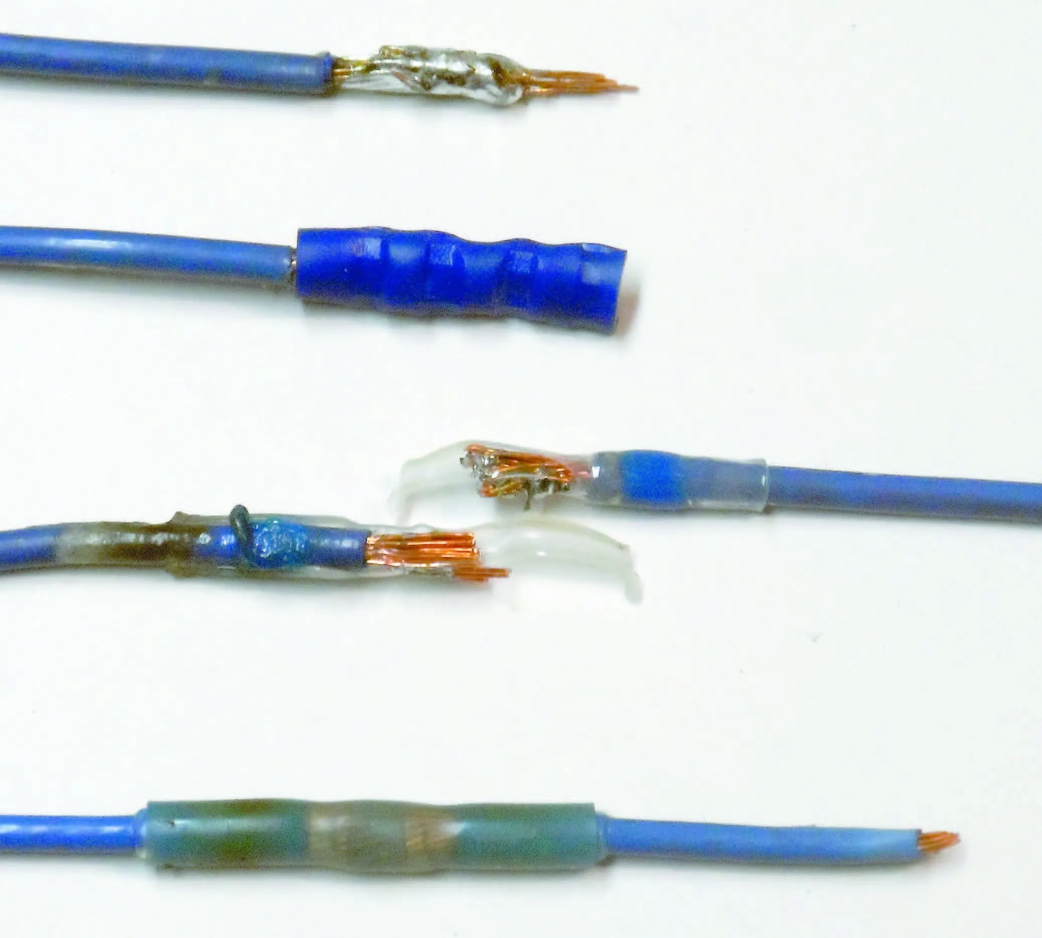
Using a heat gun on the low setting (400 F surface temperature after three minutes) the heat shrink tubing and adhesive functioned exactly as we have learned to expect, shrinking to fit the wire and sealing the ends. (The heat-shrink temperature is approximately 130 F). However, after three minutes, the solder, which has a melting point of 280 F, had not melted. On the high setting (655 F peak surface temperature after 3 minutes) the solder began to flow in about 30 seconds for Electriduct and 90 seconds for 3M.
The high setting is dangerously hot for many materials. Remember Ray Bradburys Fahrenheit 451? This is the temperature when paper smolders and pizza boxes catch fire.
We’re concerned that working in tight spaces with a heat gun on a high setting can damage electronics, fry wire insulation, and even pose a fire risk. Applying heat shrink alone is safe because it requires lower temperatures and less time.
Copper wire is very efficient at conducting heat away, and the wire is insulated from the hot air by the heat shrink tubing.
In one trial of the Electriduct connectors, the heat shrink split at the end before the solder began to flow. In another, the center burst while the solder was molten, allowing solder to flow outside the connector.
The other four trials, by comparison, were uneventful. The 3M connectors required considerably more heat, but they did not deform, crack, or discolor, and the results appeared sound.
The solder core fell out of one of the 3M connectors before we started. If we had not seen the bits in the bag, it is possible we could have missed this. Check for all fittings before use.
All of the completed samples showed good continuity and low resistance under load. But so would wires that were twisted together.
We then moved on to pull testing. Control samples that were either crimped or soldered by conventional methods always failed by breaking the wire, substantially exceeding ABYC and UL standards. Unfortunately, the Electriduct connectors pulled apart far below standard requirements and exhibited no more strength than the heat-shrink tubing alone. Solder penetration and wetting of the wire was very poor, only spattered onto the outside of the wire bundle.
By comparison, the 3M connectors always exceeded the strength of the wire, the wire failing well away from the fitting. Wetting and solder penetration were excellent; we theorize the longer heating time and greater temperature made the difference.
Conclusion
Quality varies. The 3M connectors were stronger than the wire and about as good as any soldered connection can be, other than the lower solder melting point (315 F vs. 361 F). On the other hand, cheap connectors may look good, but in reality be no better than twisting wires together and covering them with tape. Under no circumstances buy no-name solder seal connectors.
We can understand why ABYC does not approve such methods and we concur. There is no means to visually judge the quality of the fittings and no way to confirm that the finished joint is any good-other than pulling it apart. 3M did their homework, but Electriduct did not. Were also concerned about the security of overheated circuits.
Given the added risk of fire on board that these terminals can present, we’re going to remain conservative sticking with crimp connections until something is proven better.

Heat-and-seal connectors were neither easier nor more reliable than crimped connectors. For more on the tools and crimps see: “Strippers and Crimpers,” PS August 2003, “Crimp Connections,” June 1998, and the Inside PS blog post “Wiring Tips.” )
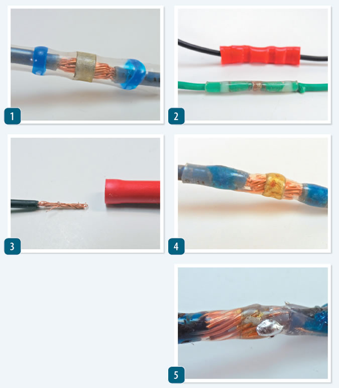
1. Once the crimpless connector is in position, heat is carefully applied with a heat gun.
2. The crimped butt connector (red) is broader than the solder-less butt connector from 3M.
3. Doubling smaller wires before crimping can ensure a closer fit.
4. After testers heated the Electriduct connector with a heat gun according to makers instructions, the embedded solder was still not yet fully melted, adding little or no conductivity. The clear plastic tubing appears to provide a good seal, but the solder itself is only softened slightly.
5. Increasing the temperature liquified the solder and allowed it to penetrate between the strands. However, the higher temperature caused the plastic insulation to melt, allowing the solder to escape.


One problem with some crimp connectors: the insulation can lap over the edge of the lug. This means that no matter how tight you get the screw or nut, you will NEVER have good contact netween the lug and the underlying busbar or device
This was not a valid test, the wire used was not Marine cable, it was un-tinned bare copper automotive wire. Bare copper wire is harder to solder without fluxing and pre tinning the wire. Non-crimp low temperature solder butt connectors with adhesive heat shrink can provide an excellent waterproof wire connection when used with clean tinned wire and when properly heated to melt the low temperature solder and shrink the heat shrink sleeve. Proper Crimp connections require operator skill or the use of the correct type of expensive ratchet crimp tools to insure the crimp barrel and wire are fused together. Improper crimping can lead to loose connections, breakage of the heat shrink sleeve and a very poor connection. Even a properly Soldered Butt connection with added Adhesive lined Heat shrink tubing will generally result in a better electrical connection than Crimp connectors.
No knowledgable marine tech is going to butt joint a wire. A Western Union or a T splice would be used, then soldered, covered with electrical conducting grease and then shrink tubes. I also finish off with a colour correct covering of electrical tape
All wires should be supported with vibration In mind.
I use a micro butane torch and flux cores silver solder.
I will put that joint up against any fastener!
This is an instance of PS not doing it’s homework and coming up with invalid statements conclusions. Who the heck did this testing. Not a marine electrician.
Whatever is the purpose of even trying to test something that is not ABYC compliant?
No electrician would use solder-only connectors.
YOU USE crimp, then heat shrink/solder terminals!!!!
These are available from tons of suppliers. Test the CORRECT products. My presumption isthat, whomever did the testing, doesn’t know about the range of products or the methods that are out there.
Del City
NAPA
NEF
Wiring Depot
WayTeck
Multilink
Kimball
All the above carry crim-then shrink/solder butts. SOME carry the same in terminals (rings, quick-disconnects, forks, etc.)
-Ken