

This is Part II of a three-part series detailing the installation of a complete inboard engine system into our highly modified Cape Dory 36 Far Reach. We sailed the boat for five years without an inboard engine, so this was a project “from scratch” as there were no existing engine beds, shaft log, wiring, fuel system etc. Part I provided background, and details on engine and propeller selection (see “Marine Diesel Repower, Pt. 1,” PS April 2023). We selected a Beta 25HP three-cylinder diesel engine with a two-blade FlexOFold propeller. Part I concluded with the drilling of a successful exploratory hole for the shaft log.
SHAFT LOG
The engine required a 1-inch propeller shaft. For the shaft log, I purchased a 4-foot-long, G10 tube with a 1.5-inch ID and a 1.75-inch OD from McMaster Carr. I also purchased a 4-inch long Johnson cutlass bearing with a 1-inch ID (for the prop shaft) and OD of 1.5 inches (to fit in the stern tube). Next, I chased the exploratory hole with a 2.25-inch hole saw mounted on an 18-inch long ¼-inch bit. I carefully drilled through the sloping hull at an oblique angle and into what would become the aft end of the engine compartment. The wide diameter hole saw would give me a little wiggle room to best position the G10 stern tube and provide some space for thickened epoxy to fit around the tube and the hull. With the stern tube temporarily in place, I could determine where to cut the rudder.
The next step was to cut 5 inches off the top of the rudder. To seal the cuts, I epoxied a ¼-inch thick manufactured fiberglass to the open top of the rudder and to the section I had cut off. Next, I epoxied the section of the rudder I cut off to the underside of the hull. The top of the rudder became, in effect, a skeg extension that followed the original hull profile and extended it five inches deeper. This extension allowed me to locate the shaft log at a lower position as well as to secure it to the hull. It took a couple of days to flare the new skeg around the rudder-post. That done, I was ready to fabricate a bracket to lock the stern tube to the hull/skeg. I used ¾-inch manufactured fiberglass which I cut with a jig saw and shaped into a profile that would fit the long stern tube and epoxied it to the new skeg.
Finally, it was time to permanently install the shaft log. I desired the shaft log to extend into the boat only as far as necessary to accommodate the stuffing box. Pushing the shaft log further into the boat would require moving the engine forward, which would create additional challenges for the engine box and companionway ladder. Every step of the project had to be considered in a holistic manner.
I needed a cool day for epoxying the stern tube in place, which I did by mixing large batches of epoxy with colloidal silica that I loaded into large plastic syringes and squirted into the gaps around the stern tube. Once the epoxy began to tack-up I began applying four pre-cut layers of 1708 biaxial in an overlapping manner. I squeeged out the excess epoxy and covered both sides with peel-ply to leave a smooth finish as it cured.
ENGINE TEMPLATE
With the shaft log in place I installed the stuffing box. The beds had to be precisely built and installed so the flange on the engine transmission would mate perfectly with the flange on the prop shaft. Earlier, I had built a basic engine template and used it to see if the engine would fit in the allocated space. I now refined it further and attached the same engine feet to it that would be on my Beta 25. I checked the measurements of the template and engine feet to ensure they were an exact reflection of the Beta schematic drawing.
I built wood plugs for the shaft log, one for each end, carefully drilling a hole in the center of each plug with the hole in the forward plug a little bigger. I ran a string through the plugs (knotting the one on the aft most plug) and then through the two wood brackets I attached to the template front and back. The brackets depicted the precise centerline of the transmission coupling with the centerline of the engine. When I pulled the string tight, I kept repositioning the template until the string did not touch the sides of the hole in the forward plug in the shaft log or the notches in the wood brackets representing the centerline of the crankshaft. When aligned as such, and clamped into place, I could then take measurements below the bottom of the engine feet so I could make the engine beds.
ENGINE BEDS
I chose to build the engine beds by laminating BS1088 plywood. BS1088 is built with water and boil-proof resorcinol adhesive to standards established by Lloyd’s of London. I planned to install ¼-inch bronze plate where the feet would be positioned on the top of the beds and cover them with ½-inch G10 plate and cover all of it with four layers of 1708 biaxial and epoxy. I planned to drill and tap for the bolts that would secure the engine feet to the beds without nuts.
To get the measurements I bolted ½- and ¼-inch plywood to the bottom of the engine feet to simulate the ½-inch thick G10 and the ¼-inch of biaxial that would cover the beds—otherwise the engine would sit higher than I anticipated when installed. The key to the whole project was the string pulled through the plugs in the stern tube; this had to be tight and precisely aligned so that it did not touch the forward plug or the flanges representing the centerline on the engine.
Using doorskin ply and a hot glue gun, I then built templates for the plywood-laminate beds to which the engine would be bolted. I cut, stacked, and then epoxy laminated ½-inch marine ply to match the templates. I achieved a close fit, then temporarily attached the beds to the plywood plate under the engine feet. Using slips of paper to find the high spots in the engine beds, I was able to get a close fit with the hull by shaping the beds with cabinet files and a high speed grinder.
I brought the port side bed back to my workshop and applied biaxial cloth to the outboard side since it would be flush with the fore-and-aft bulkhead when installed. After the fiberglass cured, I took it back to the boat, and with the string still perfectly aligned, I used thickened epoxy to glue the beds to the hull held in place by the engine template. I let them cure overnight.
The next day I removed the engine template. I set it aside as I would need it later for locating and tapping the bolt holes for the engine mounts. The beds were held firmly in place by the cured epoxy. I applied thickened epoxy for fillets and epoxied the 1/2-inch G10 plate to the top of the engine beds and covered all of it with four overlapping layers of 1708 biaxial. When the beds cured they were rock solid.
DIESEL FUEL TANK
One of my concerns about installing an engine in the boat was the loss of valuable storage space. Next to the engine, the fuel tank occupies the most space. The original 50-gallon tank was located in the bilge. I removed it during the rebuild and in its place I installed three tanks to hold 70 gallons of water. I did not want to give up space in the cockpit locker for the fuel tank. But, there was an unused space behind the stove/oven and forward of bridge-deck bulkhead that looked to be about the right size and it was not too far off the boat’s centerline. I removed the stove and built a plywood mock up to fit in the space. I liked the fit. I performed the basic calculations and determined it would hold about 19.7 gallons.
I wanted a cruising range of 250 nautical miles under power on flat water. At a projected fuel consumption rate of about 1 to 1.5 liters per hour at 5 knots cruising speed, this would yield a range of about 250-350 nautical miles. Although 20 gallons isn’t a lot, I figured I would not use an engine much just due to my nature. Also, the fuel in a smaller tank would be less likely to go bad because it would have a higher turn-over rate.
Another advantage of the tank located below the bridge deck was that I could install the fuel fill directly above the tank thus making it possible to use a simple sounding stick to measure the fuel level. And lastly, the tank would be simple to remove if the need ever arose.
I made a drawing of the tank and sent it off to several tank builders. The bids were all about the same ($500). I chose Florida Fuel Tank (located in NC) because they had good reviews and they were not too far away. They were helpful and seemed genuinely interested in my project. I asked them to install a baffle and an inspection cover. They sent me a precise drawing signed off by an engineer for me to approve. A month later the aluminum tank was ready.
I installed the tank and it fit perfectly. I drilled a hole through the bridge deck and back filled the core with epoxy then installed the original Spartan Marine bronze fuel deck fill that I had kept. I built a removable varnished V-groove mahogany box around the fuel fill hose and varnished it so it blended in with the rest of the cabinetry.
inspecting the new custom fuel tank designed by Florida Fuel Tank.
ELECTRICAL
I decided to relocate the previously semi-hidden Blue Seas 8 breaker distribution panel to more accessible location under the companionway and combine it with the engine instrument gauge panel. I did not want the engine gauge panel in the cockpit footwell where it could get flooded with seawater or on the back of the cabin top because I find it generally unsightly and distracting to sailing. However, I wanted the gauges to be easily accessible to the cockpit (including starting and shutting the engine down). I checked the ergonomics and found I could lean in through the companionway and look back under the bridge deck and easily see the instruments, flip switches on the panel, and start and shut down the engine. I built a hinged mahogany panel and sliding doors to both hide the gauges and to protect them from any water that might find its way below. Relocating the panel required that I reroute a number of wires, label, and bundle them so they are easy to trace and remain clear of any damage. I replaced a few wires that were too short for the new location with marine grade tinned wire using heat shrink adhesive connectors and high-quality wire stripping and crimping tools.
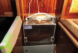
BATTERIES
For five years I sailed with a single 100 AH Lifeline AGM battery charged only through a 30-watt solar panel. It worked well. But with the new engine I also decided to replace my tried-and-true kerosene navigation lamps with LED lights. Thus, I decided to increase the size of the battery bank and solar panels though still keeping the solar panels on flexible 10-foot power cords, allowing the panels to be easily moved around on deck to keep them in the sun. I chose T105 Trojan 6-volt, wet-cell batteries wired in series for 12V due to their legendary performance, low cost, and ability to be charged with an inexpensive easy to replace automotive style alternator standard on the Beta engine. For solar panels I chose two Zamp Obsidian Series 45-watt low profile glass panels. I mounted them to ¼-inch acrylic backing plates I purchased from McMaster Carr so I could secure them with lanyards to the inverted dinghy or other locations on deck to keep them in the sun.
ENGINE BOX AND CABINETRY
To accommodate the engine I needed to make a few changes to the cabinetry around the companionway ladder. I lengthened the starboard side fore-and-aft bulkhead which served as the side of the engine box using V-groove varnished mahogany finish to make it all blend in with the rest of the interior. I extended the workbench top about 14 inches along with its pull-out drawer. I modified the kickplate at the base of the companionway so it could be removed for a better engine access. The biggest change was to cut down the mahogany and teak companionway ladder to use the top of the work bench/engine box as the second step down from the companionway.
FINAL PREPS FOR THE ENGINE
One of the advantages to doing your own work is you can incorporate some very useful modifications. I built a rack/bracket system on the starboard side of the engine beds to hold the stock and shank of the Luke Storm Anchor. I also built a drip catch with a hose barb under the prop shaft stuffing box with a ¼-inch hose to divert any water seepage via the stuffing box to a one-gallon jug in the bilge. My bilge would stay dry without the need for a failure-prone, hard to repair, dripless prop shaft seal. But the most useful modification was a full-length removable drip pan under the engine, which I think every boat should have.
Before I installed the engine, I installed the fuel system to include a Racor filter and the raw-water intake. I painted all the fiberglass work in the engine compartment with Interlux grey Bilge-kote and then installed 1-inch thick Sound-Down to reduce engine noise and vibration.

INSTALLING THE ENGINE
With all the prep work complete, the last thing to do before installing the engine was to drill and tap for the bolts securing the engine feet. Nearly everyone I talked to recommended I install the engine first, line it up on the beds to check the alignment then drill for the holes. But, I was very confident the template was accurate and my work precise. So, I brought the template back into the boat. I reran the alignment string. I positioned the beds where my triple checked measurements indicated it should be positioned. Then, I marked the holes and removed the template. I drilled down through the biaxial, through the ½-inch G10 and through the ¼-inch bronze plates laminated into the engine beds. I tapped the deep holes for 3/8-inch bolts.
I installed a 1-inch OD fiberglass tube as a shaft mock up. On the inboard end if this mock shaft, I installed the Beta shaft flange, which marries up to the flange on the transmission. Later, once the engine was bolted in place, this mock shaft would help me determine the precise length for the stainless-steel prop shaft. With the mock shaft and flange installed, we used a rented forklift with a chain-fall and lowered the engine down into the boat while I guided it onto the engine beds.
I positioned the feet over the holes and bolted the engine down. I pushed the prop shaft inboard until the flange made contact with the transmission flange. The alignment was absolutely perfect. And while I performed due diligence with a feeler gauge for the coupling alignment, there was essentially no adjustment to make.
The next order of business was to get the prop shaft machined. I took the fiberglass shaft mock up, the flange and the FlexOFold two blade propeller to Bircher Machine Shop in Moorehead City. Jim Bircher recommended Aqualoy 22 stainless steel which has excellent corrosion resistance and strength in diameters smaller than two inches. I got the shaft back in a week and the fit was perfect. I installed the Beta Marine flexible coupling between the transmission and the prop shaft flange and tightened down the engine feet to the beds.
EXHAUST SYSTEM
The exhaust system does not get the attention often associated with the engine, but it is a critical and life-saving component of the engine system. The exhaust system prevents poisonous exhaust gases from entering the crew compartment and at the same time ejects sea water from the boat used to cool the engine while also reducing engine noise and back pressure.
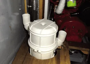
A waterlift muffler is an important part of the system. A waterlift muffler collects the sea water after it passes through the exhaust elbow mixed with exhausted gases. The water collects in the muffler but is forced out the of the muffler and along the exhaust hose and out of the boat by the pressure of the exhaust gases building in the muffler.
My engine installation guide provided me essential info. A key part of the instructions was the requirement that the outlet of the exhaust elbow be a minimum of 12 inches above the inlet of the muffler. The reason for this is to ensure water cannot back-siphon into the engine when it is shut off causing destructive hydrolock—basically water flowing into the engine cylinders. Because the engine sits low in the boat it can be hard to find the space to get the muffler low enough to work properly.
I chose a Vetus NLP 2 muffler with rotating inlet and outlet fittings to give me max flexibility in making it fit in the confined space of the engine compartment. I glassed into the hull a bracket to hold the muffler as low as possible.
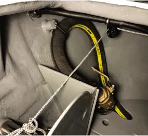
With the muffler installed, I routed very flexible Vetus Slag 50 (2-inch ID) wet exhaust hose through the port locker and into the lazarette. An added challenge was avoiding interference with the control lines of the Cape Horn windvane, which are also routed through the lockers. You can also add anti-siphon vents in the exhaust system to prevent back-siphoning, but I did not want to depend on valves notorious for clogging. Both the exhaust elbow (12-inches above the waterline) and the exhaust hose (36-inches above the waterline) would prevent siphoning but I went one step further.
I installed a Groco bronze 2-inch ball valve at the end of the exhaust hose just before it connects to the exhaust flange under the transom. The purpose of the ball valve is when closed it eliminates any chance of big swells back-flooding the exhaust system when running downwind offshore. The danger of the ball valve is if you forget to open it and attempt to start the engine you will damage the engine. To prevent that from happening I hang the engine ignition key on the ball valve handle whenever it is closed.
FUEL SYSTEM
I carefully reviewed the ABYC standards for engine installation. I chose a Racor 500 fuel water separator and installed it so I could change the filter without crawling into the engine compartment. I installed ball valves to shut off the fuel and also a fuel tank vent line to the transom using one of the original Spartan Marine vented barbs I saved during the gutting of the boat.
THROTTLE CONTROL UNIT
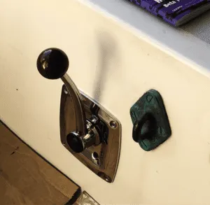
The Vetus SISCO side-mount, single-lever, 316 SS throttle control seemed like the best-made throttle control unit available. The forward end of the cockpit was the best location ergonomically when under power but when sailing, the handle would surely get tangled in the jib and mainsheets. Thus, I installed it toward the after end of the cockpit where it was easily within reach of the helm, but out of the way when sailing. The controller uses two cables: one runs to the throttle lever on the engine and the other to the transmission. After determining the required length of the control cables I visited a local marine consignment shop. Unbelievably, they had two in-the-box cables of the exact length I needed and approved for use on the cross parts list provided with the Vetus controller. I paid $20 each.
Assembling the controller was straightforward. I routed them to the corresponding engine and transmission linkages, clamping them in place so they could not move out of position. I was cautioned to make sure the transmission lever was fully engaged when the control handle was in forward and reverse, otherwise excessive wear on the transmission internal components would occur.
TEST RUNNING THE ENGINE.
With the engine supporting systems installed, all I had left to do was plug the provided engine wiring harness into the matching receptacle on the engine and wire the starter into the ignition and electrical system.
I poured five gallons of diesel fuel into the tank from a fuel jug, carefully marking my sounding stick in the process. I began the priming process, but could not get the engine to prime. Fuel from the tank would not make it to the fuel filter.
After talking to a trusted advisor I removed one sharp 90 degree brass fitting in the fuel line before the filters. I also added a somewhat controversial priming bulb, These bulbs are made for gas and not diesel, so they can break-down over time and leak. I plan to keep an eye on mine and replace it as necessary. (Another more common option would be to install a 12-volt electric lift pump that is rated for diesel fuel.) With a few squeezes of the bulb, the Racor filter filled immediately. I then followed the priming steps in the Beta manual for pulling the fuel from the Racor to engine.
I disconnected the raw water hose from the seacock and positioned it in a 5-gallon plastic bucket. I filled it with water. The moment of truth arrived. I turned the key and the engine instantly fired up and idled. I matched the flow of water into the bucket with the water being pulled out by the raw water pump. I checked the exhaust to ensure water was flowing through the system. I ran the engine for 20 minutes to bring it up to full operating temperature. I kept an eye on the oil pressure and the alternator. There was no sign of oil drips in the pan below the engine. Then I shut down the engine.
At this point the engine installation was complete. I was pleased with how it fit into the boat. Although we lost some storage space, overall it looked like it was designed to be there.
In next month’s issue I’ll describe the sea trial of the new engine, how we calibrated the tachometer, the steps we took to change the pitch of the two-blade folding propeller to maximize engine performance, and my general impressions of the addition of an inboard engine to the previously engineless Far Reach.
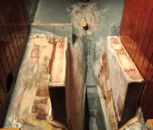
Some significant glasswork was required to install the new offset shaft log.
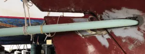
1. With the stern tube temporarily in place I could determine where to cut the rudder.
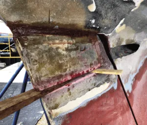
2. After cutting off the top five inches of the rudder, I epoxied that section off to the underside of the hull recreating the original hull profile.
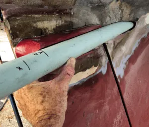
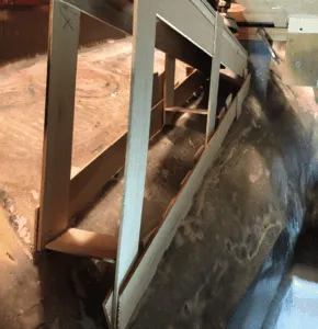
3. I cut and shaped ¾-inch manufactured fiberglass into a profile that would fit the long stern tube and epoxied it to the new skeg.
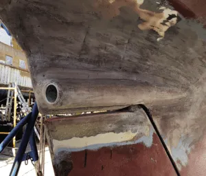
4. Large batches of epoxy thickened with colloidal silica were squirted into gaps around the stern tube to fix it in place. Peel-ply laminate left a smooth finish.
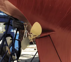
5. The two-bladed folding Flex0Fold propeller was mounted on a corrosion resistant Aqualloy 22 shaft.

A taut string drawn through the center of the shaft log was the essential guide around which the engine beds were designed and built.
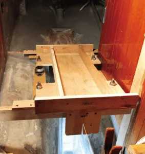
1. Plywood bolted to the bottom of the engine feet simulated the G10 and biaxial that would cap the plywood laminated engine beds.
2. Door skin was hot-glued to create a template for the engine beds.
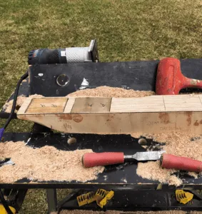
3. The engine beds were made by stacking, gluing, and shaping
1/2-inch BS-1088 plywood.
4. A top layer of 1/2-inch G10 was laminated to the top of the beds.
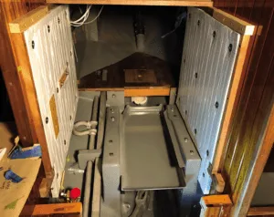
5. With the engine beds painted with Interlux Bilge-kote and the one-inch thick Sound Down insulation in place, the beds were ready for the engine to be dropped into position.


Your article is so thorough and helpful with parts lists and thought process , as you say holistic approach such as what will be the impact of this or that when sailing!
Thanks. Glade you found the article useful.