

Are you one of those sailors who believes there are too many holes in the hull of your boat? Have you ever wondered if you could install a depth sounder transducer inside the hull that eliminates the need for a hole while retaining the performance of your depth sounder? In this report, I will share how we successfully answered those questions with our own boat.
I sailed my newly rebuilt engineless Cape Dory 36, Far Reach, about 7,000 miles and two round trips between NC and the Virgin Islands with only three through-hulls—two for cockpit scuppers and one for the galley sink drain. For determining depth, a lead line worked well. I enjoyed casting the lead, an act as old as sailing itself. I used a 3-pound lead on 12 fathoms of ¼-inch, three-strand line. It was marked every fathom. I also made an easy- to-attach, 8-fathom extension for when I needed to sound at greater depths.
In 2021 I installed a 25-hp Beta Marine diesel with a two-blade folding propeller (See “Diesel Repower From Scratch Pt. 1”). Now that I had a reliable diesel engine with a 75-amp alternator and a larger battery bank supported by 90 watts of solar collection, it seemed logical to replace my simple though reliable lead line with an electronic depth sounder. However, I did not want to drill a hole in the hull to install the transducer. While I knew inside-the-hull transducers were common, I knew neither the specifics of the installation nor the effects on depth sounder performance. One caveat I learned up front—inside the hull transducers typically will not work with cored hulls. The hull needs to be solid fiberglass, like Far Reach, or thin aluminum.
Selecting the Depth Sounder
While the focus of this article is on the transducer installation, it seems pertinent to describe the decision process for the selection and installation of display unit as well.
I knew from the beginning I wasn’t interested in multifunction units or fish-finder/depth sounders or units meant to network with other instruments, or those that required learning complicated button sequences to display the information I needed.
My philosophy is the same for all the systems on the boat—devices should be simple, stand-alone units that can work independently. It’s far easier to troubleshoot a problem when systems are not tied together. I understand fully integrated networked systems are all the rage now but that goes against my “keep it simple” philosophy. My focus is to keep my offshore boat and its systems simple, rugged, reliable, effective, affordable, and easy to maintain. Less is more.
Research
I began my research by checking the archives of Practical Sailor for depth sounder tests and evaluations. While there were recent evaluations on combination fish-finder/chart plotters and portable sounders, the last evaluation on stand-alone depth sounders was quite a while ago (“Just the Numbers, Please: A Stand-Alone Sounder Sampling”). Though the information was dated, I still gained insight on things to look for in a depth sounder. My attention was drawn to the affordable though diminutive Hummingbird and Hawkeye depth sounders as well as the larger more expensive Raymarine i40 and i60 units. A quick internet search revealed all these units were still available. That alone seemed a good sign.
I eliminated the Hummingbird quickly because the website was confusing, the focus was on power and fishing boats, and there were several negative reviews.
Continued research revealed generally good reports on the Hawkeye sounder which was corroborated by sailors on the Cape Dory Forum and on the Cruisers’ Net (www.cruisersnet.com). The HawkEye required a 2-inch diameter hole. While the display screen was also about 2-inch in diameter, I could find no information on the HawkEye website about the size of the digital sounding numbers. In the 2003 evaluation, Practical Sailor reported they were 7/16-inches tall which is quite small when viewed across the cockpit of a 36-foot sailboat, and the numbers on the current model didn’t look any bigger.
Hawkeye Sounder
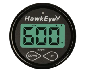
The HawkEye is a stand-alone unit with no capability to be networked, which met my requirements. It had good reviews for low cost and reliability. I downloaded the installation manual and reviewed the instructions for installing the Airmar P19 transducer inside the hull. It was ambiguous when it came to addressing deadrise (the downward angle of the hull measured in degrees from horizontal), explained in detail below. There were several online testimonies about how well they worked glued to the inside of the hull with silicone as an adhesive. However, I found no empirical evaluation on accuracy.
Online comments suggested the backlight was always on, which would draw power and unless fitted with a shade, could interfere with night vision. While the unit was affordable at about $125 including the P19 transducer, I ultimately rejected it for several reasons. There was no definitive information on how to install the transducer inside the hull. The digital display was small (some sailors reported it could be hard to read). The deal-breaker, however, was the 30-foot transducer cable. I had measured the circuitous route the wire would take from the display unit to the planned transducer location and 30 feet left little margin for error.
Raymarine Sounders
As I continued to research the few stand-alone sounders still on the market, the ones that kept attracting my attention were the Raymarine i40, i50, and i60 depth sounders. Raymarine is a well-known manufacturer of high-end marine electronics from depth sounders and chart plotters to wind instruments, radar, and auto pilots.
The Raymarine website provided very little information on the units other than general specifications. So, I downloaded the installation manuals and read through them. I quickly ruled out the more affordable i40 because I didn’t care for the rectangular shape and it came with only 30 feet of transducer cable—just like the Hawkeye. I also ruled out the most expensive i60 because its principal feature focuses on integration into wind velocity and direction instruments, capabilities I did not need. So, I focused on the i50 (part# E70148) because its purpose was limited to depth using the included Airmar P319 Transducer.
Raymarine i50 Sounder
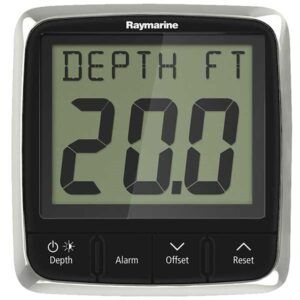
The display is almost square and looks simple to operate with just a few buttons. The numbers are large (about 1.5 inches tall) and the contrast adjustable, as is the backlight. Like the HawkEye, it has a depth alarm and the offset for the depth of the transducer location below the waterline can be calibrated on the display. Unlike the Hawkeye, it was expensive—$550 for the E70148 display/transducer package.
I carefully read the installation manual for the i50. The only provision mentioned for the inside-the-hull installation was to purchase a special Airmar P79 transducer that comes with an optional angled, plastic housing to be glued to the inside of the hull. Once installed, it is filled with antifreeze into which the transducer is inserted and screwed down in place. The fluid ensures there is no air between the transducer and the hull of the boat.
When I was a kid, we had a Danforth flashing echo sounder on our family sailboat installed in a similar way. The transducer was mounted in a box glued to the inside of the hull and filled with mineral oil. It worked, but the box often leaked mineral oil into the bilge, and we would have to top it off again. I wanted no such mess in Far Reach. I wanted something simpler.
Time to Improvise
While I found a few testimonials online about gluing the i50’s transducer to the inside of the hull with silicone or epoxy, they did not account for the deadrise, which was a challenge in my case. It seemed to me if the transducer was not positioned vertically, it would not provide accurate depth under the boat. However, the installation manual stated even with the P79 transducer, the maximum deadrise was 20 degrees. The deadrise in my chosen location (opposite the mast on the starboard side) was 27 degrees.
I found endless debate online about the characteristics for the many different transducers available—literally dozens of them. It was maddening to read one thing only to read the opposite about the same transducer somewhere else. The manufacturers are not helpful, as they say very little and it’s usually clouded in technical jargon. Most of their concerns appear to be aimed at accurate readings for planing powerboats. I learned to prepare for ambiguity when it came to transducer selection.
To be fair, most transducers are specific to multifunction combination fish finders. When it comes to simple stand-alone sounders, there are just a few transducers relevant to my project: the Airmar P19, P79, and P319. Some more expensive units also measure water temperature, but this feature won’t work with a through-the-hull setup.
Finding a New Way
I continued to research installation options and eventually stumbled upon a post on Cruiser’s Net by Rod Brandon, a certified Raymarine installer, with Sheen Marine. He stated he had successfully installed many transducers inside the hull by gluing them to a horizontal surface on top of an epoxy puck he created from a mold. I contacted him via email and he kindly responded back describing the technique he used to install the transducer.
He said he had the best success with Raymarine sounders using the P319 transducer versus the P79 which is normally used with the optional antifreeze filled plastic housing. That was good news for me, as the i50 package sold by Defender Industries (www.defender.com) came with the P319 transducer. So, I ordered it.
Installing the Display
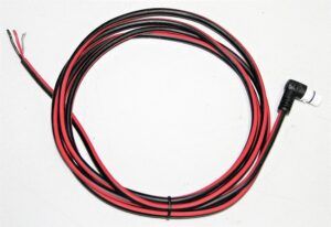
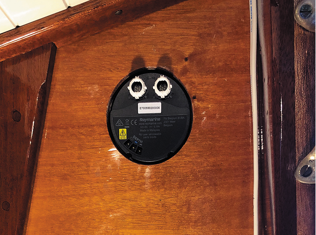
The depth sounder arrived in a box with the display, two display covers, installation template, a P319 transducer with 45 feet of wire, and a 12-inch SeaTalk Spur for connecting the sounder to a NEMA 2000 network (which I did not need except for the power connection), and the installation/user manual.
Installing the display was straightforward. Since I did not have an existing depth sounder I had no need to fit the display into an existing hole.
1. Choose Location, Sketch a Plan
For the location, I chose the aft end of the cabin-top on the starboard side of the companionway. Before I drilled, I sketched out a plan to cover the back side of the display unit, as well as how I would run the wires for the transducer and power supply, and how I would conceal them. Raymarine components can be networked off a single wire backbone via spurs for each piece of equipment. I did not want or need any NEMA 2000 network capability.
The i50, however, also had a connection for a direct power supply, using a SeaTalk connector, which I chose to use. I did not like the standard plug for the Seatalk because the straight fitting stuck out and would require a larger box to cover the back of the display. With more research, I located a right-angle Seatalk direct power cable (part# A06070) from Marine Surplus (www.marine-surplus.com). It’s compatible with the i50 for $12 including shipping. The right-angle connector allowed me to build a smaller lower profile box to conceal the back of the sounder display.
2. Tape Off Fiberglass, Drill Hole
Once I determined the exact location for the display, I taped off the fiberglass to protect the gelcoat and Awlgrip paint and help prevent chipping. I used a 3.5-inch hole saw to make the hole for the display.
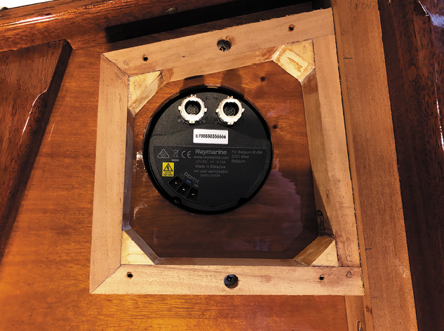
3. Make Cover Box
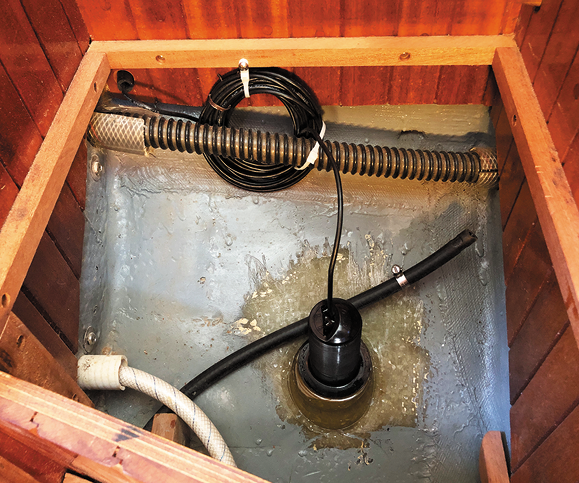
Next, I used scrap African mahogany to make the cover box and the trim for hiding the wire inside the boat. The mahogany would also blend in with the rest of the interior. I installed the sounder display and test fit the trim. Satisfied, I removed the trim, varnished it, then reinstalled it. To determine the location for the transducer, the boat had to be in the water.
Installing the Transducer
After I launched Far Reach and moved her into the slip, I set about installing the transducer.
1. Determine Water Depth
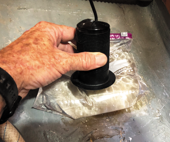
The first step was to determine the exact depth of the water over the side of the boat adjacent to the location I had selected for the transducer (opposite the mast and under the platform that supports the Refleks heater). I used a lead line to measure the depth of the water. Next, I wet the fiberglass where the transducer would be installed, and positioned a Ziplock bag of water against the inside of the hull on the same spot. I placed the transducer, vertically oriented, on top of the bag of water and my wife powered on the display while I held the transducer in place. The depth registered almost immediately. I corrected for the offset (the distance below the waterline where the transducer was located) by adding it to the depth shown on the display. A second depth check confirmed that the depth on shown on the display was now accurate.
2. Make Epoxy Puck
For my epoxy mold, I used a plastic mixing cup. I cut off the bottom of the cup and used scissors to cut a bevel in the side of the cup to match the deadrise of the hull where I wanted the transducer to be located.
3. Prepare Hull for Puck Install
I positioned the cup/mold on the hull and marked all the way around it with a marking pen; I then sanded the bilge paint off with 80 grit abrasive paper. I vacuumed the dust and cleaned the area with acetone to remove any contaminants. I used butyl rubber, rolled into a long rope-like shape, and pressed the inverted plastic cup into the ring of butyl to secure it firmly in place on the hull and to ensure the epoxy could not escape when poured into the mold.
4. Prep Transducer
Next, I wiped the face of the transducer with denatured alcohol to remove any grease or oil and lightly sanded it with 80 grit paper so the epoxy would have something to grab. I set it aside.
5. Mix Epoxy
The most difficult part of the entire installation was next. It was summer and epoxy is exothermic when mixed—meaning it gets hot as a reaction to the curing process, which occurs when you combine the resin with the hardener.
Hotter ambient temperatures can contribute to a hotter exothermic reaction, so much that the epoxy can smoke or even catch fire. So, limiting the heat associated with curing is important. I used West System 105 Resin and 206 slow hardener to help retard curing. I also planned to make multiple small batches of epoxy to avoid excessive heat associated with a single large batch.
Tip: Mix in Ziploc Bag to Reduce Bubbles
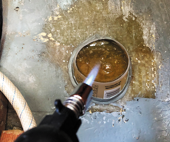
The trick is to mix the epoxy in such a way as to avoid bubbles which can adversely affect the transducer’s ability to work properly. You do not want any bubbles in the cured epoxy puck. Instead of mixing the resin and the hardener in a cup with a stir stick (the traditional way) which can induce small bubbles, I mixed them together in a zip lock bag. With the two parts poured into the bag, I zipped it closed and massaged the liquids mixing them together for about 90 seconds, careful not to introduce any air which can form bubbles. Then, I snipped off one corner of the bag and let the epoxy run out of the bag and into the mold. A few bubbles formed, but I was ready with a technique I’d learned rebuilding my boat. I had a butane micro torch ready and passed the flame quickly a few times over the surface of the epoxy. The bubbles disappeared.
6. Pour Epoxy
I made four pours over 3.5 hours to keep the heat under control. You don’t want the epoxy to fully cure between pours, just get past the maximum exothermic heat then pour the next batch. You’ll know if the epoxy is too hot by touching the sides of the plastic mold. Then, pour the next batch and so on. After each pour, I used the micro torch to eliminate any bubbles—just a few quick passes with the flame. I was anxious about the bubbles but it turned out to be the clearest pour I ever made. When it was complete, I could not see a single bubble.
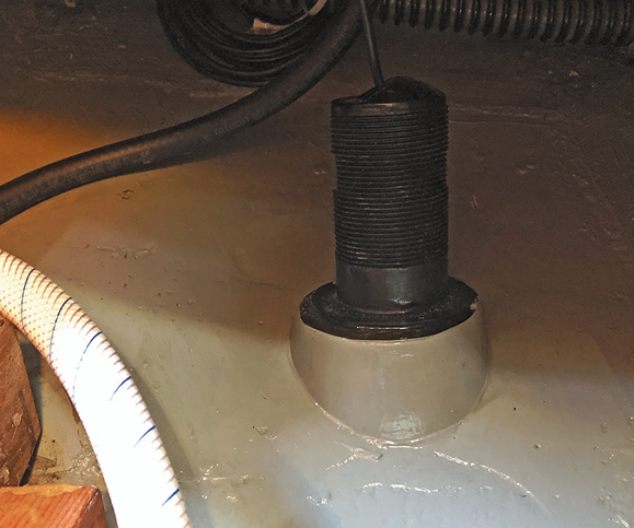
7. Mount Transducer to Puck
I waited about an hour after the third pour, allowing the puck to be very firm but not rock hard. Then, I made the last pour only 1/8-inch deep and gently pressed the transducer onto the thin, top layer of epoxy to secure it in place. I let it cure for two days.
8. Test Unit
When I returned to the boat, I turned on the unit and got a perfect reading, which I double checked with my sounding line.
9. Optional: Paint Puck
Even though the transducer is completely hidden from sight, I finished off the project by painting the sides of the puck to match the paint on the hull interior. If the transducer ever needs to be removed, it will be simple to do with a block of wood and a mallet.
Six months after installing the transducer, I sailed Far Reach to the Virgin Islands and back to NC. The depth sounder worked perfectly.
Conclusion
Limiting the number of holes in an any boat, but particularly an offshore boat, is a smart move as it reduces potential failure points in the hull’s integrity. While other transducer/sounder combinations might work just as well, my choice has worked well for me.
Although I chose the more expensive Raymarine i50 for its longer transducer wire and larger display numbers, I believe the more affordable HawkEye would be a good choice for a smaller boat where the skipper is closer to the display unit. You don’t need to be a technical expert to install a transducer inside the hull of your boat. All you need are basic skills and a thoughtful, careful, and organized approach.
Contacts
RAYMARINE, www.raymarine.com
AIRMAR, www.airmar.com
HAWKEYE, www.hawkeyeelectronics.com
MARINE SURPLUS, www.marine-surplus.com
AWLGRIP, www.awlgrip.com
WEST SYSTEM, www.westsystem.com
Consider the size of the numbers on the display and if you can see them from your normal helm position. Some sounders don’t display the data well when observed from angles or in bright sunlight. Make sure the data can be seen when wearing polarized sunglasses.
Twist the transducer power supply wires together. This is sometimes referred to as shunting the wires. This is not to be confused with a shunt, a device used to limit the flow of electricity, although they have similar functions. Shunting the wires helps to avoid electric shock at the end of the wires. Because the transducer converts any energy that strikes it into electricity, dropping the transducer could energize the wires.
Read the installation manual for insights into what components and options work for your sounder. You can often download product manuals from the manufacturers, and sometimes vendors’ websites and read them before you purchase the product.
Carefully determine the route all the wires will take between components and how you will hide them as well as access them if troubleshooting is required.
Test the location of the transducer using the water-filled-bag method or other method to ensure the desired location works.
Make multiple pours of epoxy to avoid excess heat. If it’s hot, use slow hardener to reduce exothermic heat as the epoxy cures.
There is endless debate about transducer capabilities. No manufacturer I researched specifically describes gluing a transducer to the inside of a sailboat hull, so this technique is owned and developed by boaters.

Molding the epoxy base was straightforward. The challenging part was getting rid of bubbles and preventing the epoxy from curing too quickly.
1. With the boat in the water, we tested the new transducer through a plastic bag filled with water.
2. A plastic tub used for measuring epoxy served as our mold. To allow ample cure time, several small pours were used to fill the mold. A few passes with a butane torch immediately after the pour eliminated the bubbles that formed during the pour.
3. Bedded in one final, thin layer of epoxy, the transducer was held firmly in place and the puck was ready to be painted.
4. Once painted, the transducer and puck looked like they had originally been installed by the boat manufacturer.
Some scrap African mahogany from a previous project was used to make the inside cover box. Protruding only slightly more than the display itself, the box protects the back of the display as well as conceals the black housing and wires. Once I sized the box to fit, I removed it, varnished it, and screwed it back in place.
1. The back of the display measures about 3 ½ inches in diameter. I decided on a square cover of slightly greater dimensions.
2. Two screws were enough to secure the glued-and-screwed frame for the mahogany cover.
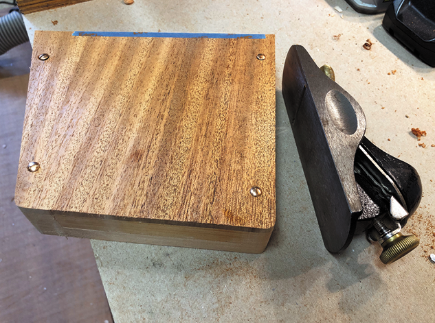
3. A few passes with a plane brings the top edge of the cover box flush with the side.
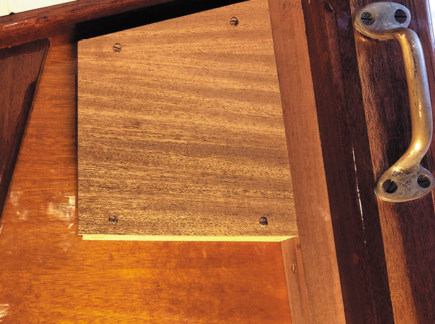
4. The varnished box literally adds a new dimension to the cabin. Undo a few screws and you can get easy access to the back of the display.
This article was first published on 27 November 2023 and has been updated.


I did this with GE silicone on my Ranger 29 years ago. worked like a charm.. just made a puddle of silicone on cleaned and slightly abraded interior hull surface and stuck the transducer in.
Thanks for the great article and explanation. I own a 30′ Cape Dory ketch and looking to replace my instruments.
Thank you for writing this article, John, and for sharing your knowledge. I will need to add a depth sounder to a Westsail 32 that I’m rebuilding and I’m sure that I’ll refer back to your writing in the coming months.