

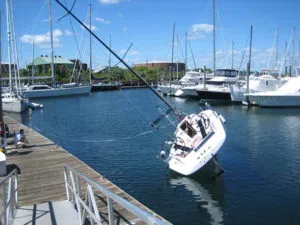
When the waves kick up, you can’t help thinking about ultimate stability. Am I feeling form stability, the stability that relies on the boat’s beam and buoyancy to resist healing? Or is it the counteracting righting moment of ballast that is keeping the boat upright? Except for unballasted racing dinghies, it’s a bit of both.
Last month, we discussed multihull stability and how both form stability (weight and beam) and dynamic stability (burying of hulls and bows) affect our ability to stay right-side up (see “Multihull Capsize Risk Check,” February 2021). In “Dissecting the Art of Staying Upright,” Practical Sailor June 2015 we discussed the GZ curve and the limit of positive stability (LPS), also called the angle of vanishing stability (AVS). We’ll review these briefly here, but for those unfamiliar with the topic of stability, it would be good to review our past articles on stability first.
Modern production boats ISO CE category certifications that are supposed to indicate their suitability for sea. Boats rated for Category A “Offshore,” and Category B “Ocean,” must also meet the latest version of the International Stability Standard IS0 12217, which specifies stability based on the boat’s mass and its AVS. Our aim with this report was to address a perennial stability question. Can an owner create a GZ curve and or determine the AVS for custom boats, modified boats or older boats that lack CE certificates or published data?
The GZ Curve
The factors involved in determining the GZ curve, or righting moment curve, is pretty straightforward. Righting moment at any given angle of heel is defined as the force applied at some distance from the heeled center line times the distance from the heeled centerline. For example, if it takes 200 pounds on the rail (6 feet from the centerline in this example) to heel a boat 5 degrees, the righting moment at 5 degrees is 200 x 6 = 1,200 ft-pounds.
In most boats the righting moment rises from zero at rest, to a maximum AVS of about 40-80 degrees of heel. Ballasted keelboats can extend that significantly.
As pointed out in the June 2015 report, it is important to understand that stability is not the same as seaworthiness. Stability is but one item of compliance among many (such as hatch area and placement) used to determine a boat’s ISO CE category. The GZ curve ignores the very significant effect of sloping or breaking waves. Cabin flooding, cockpit flooding, crew movement, gear shifting, and free surface movement of liquids in tanks are also neglected.
Any of these factors can have significant impact on stability, and will greatly reshape a boat’s “real world” GZ curve. Also, as we discussed in our September 2015 PS Advisor column, things like davits, dodgers, and in-mast furling can render obsolete your maker’s stability specs.
What does a desirable GZ curve look like? What AVS or LPS do we aim for? According to the World Offshore Special Regulations, racers will not be issued a valid racing certificate for World Sailing races if the boat’s upper limit of positive stability is less than 103 degrees (90 degrees for ORC sport boat), as measured per IS0 12217-2.
Practical Sailor recommends a minimum of 120 degrees for cruising monohulls. Boats certified by the ORC (Offshore Racing Congress) have had the shape of their GZ curve evaluated by computer, based on data obtained while taking precise measurements while heeling the boat with weights in calm conditions. The measurements help determine the center of gravity of the boat, the shape of the GZ curve, and the limit of positive stability.
With or without the involvement of a naval architect, getting accurate GZ Curve using an incline test is not the sort of thing a typical DIY sailor is usually capable of handling.


The Westlawn approach
The high-profile capsize of a number of small passenger pontoon ferries in the U.S. has prompted a search for a simplified stability testing process that the U.S. Coast Guard could apply to small commercial passenger boats. Like IS0 CE 12217, the current Coast Guard method of evaluating stability is complex, requiring detailed hull form and construction data, and calculations based on the relationship between the center of gravity, center of buoyancy, and the heeled metacenter. These measurements are not readily available for many boats, and any changes to the boat’s design or operations (number, or placement of passengers) can make the original numbers wildly inaccurate.
In 2009 the Westlawn Institute of Marine Technology proposed a simplified method of stability testing. The boat would be heeled as much as 15 degrees using weights, avoiding some of the need for detailed knowledge of buoyancy and weight distribution. This would be called the Inland Stability Standard (ISS).
ISS and Wind Heel
According to the ISS, heel induced by wind alone “wind heel” should not immerse more than ¼ to ½ of freeboard in the strongest expected wind, and the heel angle should not be more than 14 degrees. The strongest wind that you’ll use for calculation varies depending upon whether you are in exposed waters or protected waters. This is based on CFR 170.170.
The extent of freeboard immersion varies with the amount of floodable cockpit; a boat with a sealed cockpit can safely heel farther than one with a large open cockpit.
In exposed waters:
Immersion limit =
f(2LOD-1.5CL)/4 x LOD
In protected waters
Immersion limit =
(2 x f x LOD-CL)/4 x LOD
where :
f means freeboard
CL means cockpit length
LOD means length on deck
Heel angle = (wind pressure)(average distance from center of windage to center of resistance)(53.7) /((GM)(displacement in pounds))
where:
Center of lateral resistance (CLR) is estimated to be about ½ draft.
GM is the metacentric height
The wind pressure variable used will depend on sailing area:
For an ocean crossing = 50 knots or 15 pounds/square foot
For ocean coastal = 45 knots or 13.4 pounds/square foot
For semi-protected waters = 40 knots or 8.5 pounds/square foot
For protected waters = 35 knots or 6.5 pounds/square foot
Passenger heel
According to the ISS, the passenger heel limit (with all passengers shifted to one side) should not exceed ¼ of total freeboard—or ½ of freeboard if the deck is sealed or the cockpit is very small. Heel angle should never be more than 14 degrees with all of the passengers shifted to one side of the boat. This is based on US CFR 171.50. The average passenger weight in CFR 171.50 is estimated as 140, but it will likely be adjusted upward in future revisions.
Passenger heel angle = arcsin((2/3 of passengers x ½ beam)/(Displacement x GM))(Arcsin is on your smart phone calculator).
Where:
Displacement is the weight of the boat in pounds with fuel and water but without passengers, and
GM means metacentric height
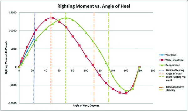
As we discussed in our 2015 report “Dissecting the Art of Staying Upright,” the GZ Curve (at right) can be used to calculate a stability ratio—the area circumscribed in the positive portion of the curve, divided by the area circumscribed by the negative portion of the curve. A higher ratio is better, and a common rule of thumb is that an ocean voyaging boat should have a ratio above 3.0.
The main article discusses creating a partial table based on heeling angles. Heeling a boat beyond 20 degrees is tricky, but if you can find boats with comparable design features and known GZ-Curves, you can visualize your own righting moment at various angles of heel, or at least roughly check the angle of maximum righting moment and the limit of positive stability. In the example case, “your boat” would likely meet or exceed the minimum LPS we recommend for offshore sailing (120 degrees), but without more information one can’t know for certain.
Once you have collected the data from your boat and other boats, you can create your own table using Microsoft Excel. Here’s how we do it.
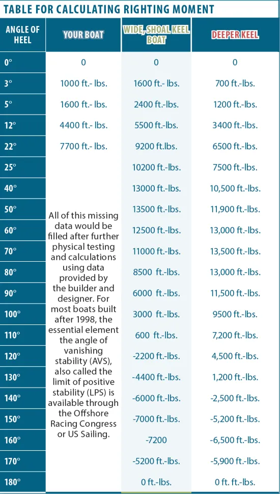
- Create a table like the adjacent table with angle and moment in columns. Although we have entered units of measure (ft.-lbs.) do not include them in your table at this time. Place any columns used for intermediate calculations (unit conversions and heel angle) to the right and do not highlight these in the graphing process.
- Highlight and select the cells containing angle of heel, righting moment., and the associated headers.
- Click “insert” on the top tool bar, and then click “scatter” from the graphing options. This will accommodate angles at irregular intervals.
- Click “Design” and a dialogue box will let you chose the title style you want. You will also be able to enter the units and descriptions for each axis.
- You can save the graph as a PDF by selecting the graph and choosing PDF on the “save as” file type menu.
Finding Metacentric height
Calculating wind heel and passenger heel using the ISS require us finding the metacentric height, GM. Hooray! We’ve finally gotten to the do-it-yourself part.
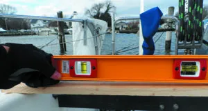
In simple terms, you take weight (perhaps crew or water jugs), move them to the rail, and then measure the heel of the boat.
You can use a 2-foot level and a tape measure to estimate heel angle as weight is added. Using this method:
Heel angle = arcsin(inches heel at end of level/24).
Now that you have heel angle, you can determine GM.
GM = (weight)(distance from centerline to weight)/((displacement) x sin(heel angle))
Voila! Plugging the GM into the formulas for wind heel or passenger heel gives you an idea of your boat’s stability — with some disappointing limitations (read on).
Limitations
This simplified approach has its own limitations. Like the LPS or GZ Curve, it does not account for the effects of large waves and is thus is only appropriate for inland waters. The accidents it strives to reduce are water taxi and excursion boat capsizes. And it only applies to monohulls.
Most problematic, it does not apply to ballasted monohulls, because the effects of ballast are not felt until greater angles of heel are reached. Thus, while calculating the Inland Stability Standard for your boat can be an interesting exercise, it is best applied to monohull powerboats.
A partial plot ?
What about creating a partial plot of the righting moment. However, because you won’t be tipping the boat very far, you’ll only get a portion of the curve. When measuring the angle of heel, remember, righting moment = weight in pounds x distance from centerline to weight.
Gradually, heel the boat and enter the data into a spreadsheet that can be used to plot angle of heel vs. righting moment
You may be tempted to add leverage by adding weight to the spinnaker halyard or winching the halyard down to the dock. So long as you accurately calculate the forces in your equations, this can be done to create a more complete righting moment curve. However, the engineering can be tricky and mistakes expensive.
For a powerboat, you can learn much about stability with just 5-10 degrees of heel. On a sailboat we are more interested in the maximum righting moment, which probably occurs at greater than 45 degrees. We also need the angle of vanishing stability (AVS/LPS), the angle of no return, which probably occurs with the mast deep underwater.
During the first 15 degrees of heel, the righting moment curve of a wide boat with good form stability and a deep keeled boat with good roll-over stability will look very much the same. It is only after a boat is heeled to a greater portion of the angle of maximum righting moment, that it becomes practical to estimate the shape of the rest of the curve, and only then with very accurate data and complex analysis.
The simplified method does a fair job of predicting the stability of unballasted powerboats, but not ballasted sailboats. At 10-15 degrees of heel they are similar, but at extreme angles they are very different.
The Wolfson Approach
The Wolfson Unit of Southampton University has also offered a simplified calculation for sailboats requiring only the following information to yield the International Ocean Racing screening stability variable (SV):
- Hull draft in feet. This is not the full draft of the boat, but rather an estimate of the depth of the canoe body depth (DCB), not including the keel. Estimate this as 90-percent of the hull depth not including the fin keel.
- Ballast in pounds.
- Displacement in pounds.
- Beam overall in feet.
- Calculate the ballast ratio:
BR = ballast/displacement
- Convert displacement to cubic feet. For seawater:
VOL=Displacement/64
- Calculate the IOR screening stability variable (SV):
SV=beam^2/(BR*DCB* VOL^0.33)
- Finally, calculate the estimate angle of vanishing stability (AVS) in degrees:
AVS = 100 + 400/(SV-10)
This method makes some assumptions about the hull form, distribution of weight, and distribution of ballast, so we refer you to pages 6-10 of this more detailed treatment: www.westlawn.edu/news/WestlawnMasthead03_Sept07.pdf.
The greatest risk for 80-percent of sailors is not roll-over, but flooding. Unless the companionway is kept closed and tightly locked in all rough weather, as soon as a boat is knocked down there is a risk that water will pour in through the open companionway, and the boat will just go down. Clearly, it must be both strong and easy to open, under load, from either side (see PS October 2015 “Bulletproof Companionways”).
Some boats have enough beam and float high enough that the companionway remain dry in a knock down. This is a requirement of some classes, such as Open 60s.
Conclusions
While our experiments can give us a better picture of how gear stowage can impact stability, a complete GZ curve remains elusive for owners of mystery boats without certification or data supplied by the manufacturer. The best a DIY evaluation with weights can do is suggest initial stiffness under sail or power, the impacts of passenger or dunnage weight.
For a rough estimate of the angle of vanishing stability, the Wolfson method works fairly well with conventional boat designs (centerboards are problematic). If your Wolfson-derived AVS is greater than 120 degrees, rest easy. If the number is lower, you can improve it by stowing heavy things deeper, removing weight from the deck and rigging, and taking steps to prevent flooding in the event of a knock-down. The opposite is also true— a boat with inherent stability can quickly drop into borderline territory with poor gear stowage, open hatches, and top-heavy enhancements.
PS Online, “In Search of Stability,” PS Online July 2018. Former PS Editor Nick Nicholson dives into theory, www.practical-sailor.com/safety-seamanship/in-search-of-stability
PS June 2015, “Dissecting the Art of Staying Upright,” June 2015. www.practical-sailor.com/safety-seamanship/special-report-dissecting-the-art-of-staying-upright
PS September 2015,“Where Can I Find Boat’s Stability Curve?”, September 2015. www.practical-sailor.com/boat-maintenance/where-can-i-find-a-boats-stability-curve
Westlawn Inland Stability Test proposal, Test Proposal for monohull power boats. www.slideshare.net/NASBLA/stability-standards-and-testing-of-commercial-vessels-on-inland-waters-iss
Westlawn institute masthead vol. 1 Nos. 2 & 3,
Two part discussion on stability by Dave Gerr, N.A. www.westlawn.edu/news/WestlawnMast
head02_June07.pdf
www.westlawn.edu/news/WestlawnMasthead03_Sept07.pdf
ORC Stability and Hydrostatic Datasheet,
An explanation of ORC stability measurement. www.orc.org/rules/Stability%20and%20Hydrostatics%20Datasheet%20Explanation.pdf


