I worked through the alternative steering geometries and forces using trigonometry. An easier way to evaluate various installations is to use a triangle, ruler, and compass and draw the geometry of each setup. Note practical socket and tiller-pin locations. The tillerpilot will need to be level, but ignore that for the moment. I made four drawings before deciding on just two options worth field testing:
Image 1. The socket is located 24.5 inches to the side of the centered tiller, just like the instructions say. The pin is located at 14 inches, 18 inches (factory recommendation), and 21 inches forward of the rudder stock, and the socket is located at matching distances, maintaining a 90-degree angle to the tiller when centered. In each position, the maximum port and starboard rudder angles are identical. The push-rod delivers maximum force, and the total helm angle ranges from 26 degrees to 42 degrees.
The 14-inch position meets my average condition tacking requirement (40 degrees). It may fall a little short of optimum in a heavy seaway, but I can make up the difference with better technique. The 14-inch setup requires the most modification to work on our F-24, but it achieves performance that is closer to what we expect.
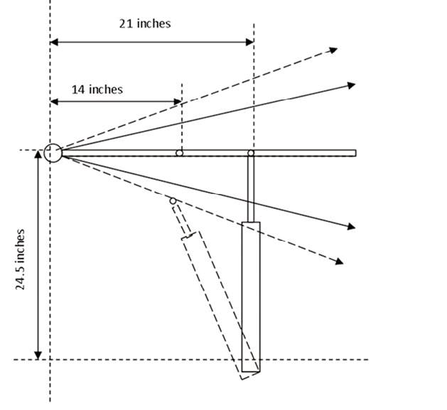
Image 2. We tried keeping the socket at 21 inches and moving only the tiller-pin to 14 inches. The range to the far side of the cockpit (when making a turn to starboard) is barely changed. The range on the near side (port turn) improved, but at the cost of terrible leverage, resulting in 2½ times the push-rod force (45 pounds) required compared to the standard position. Even with this very light boat, this exceeds our preferred force limits.
We also tried this setup with an extended push-rod. Using an .8-inch extender on the push-rod, the tiller range was centered and performance improved, but the leverage in a starboard turn was still poor.
VALUE GUIDE: CORSAIR F-24 HELM DATA
| TYPICAL TACKING DATA | ||
|---|---|---|
| HELM DATA | DEGREES OF HELM (TOTAL) | MAXIMUM HELM FORCE (31-INCH TILLER) |
| TYPICAL TACKING HELM | 20 degrees (40 degrees) | 10 lbs. |
| MAXIMUM ANGLE OF HELM APPLIED WHILE TACKING | 30 degrees (60 degrees) | 10 lbs. |
| TYPICAL WHEEL STEERING RANGE | 35 degrees (70 degrees) | 10 lbs. |
TECH GUIDE: TILLERPILOT INSTALLATION
| (1) VARYING TILLERPILOT MOUNTING SOCKET AND TILLER-PIN LOCATION | ||
|---|---|---|
| DIMENSION A (MOUNTING SOCKET’S DISTANCE FORWARD OF RUDDER STOCK) | MAXIMUM RUDDER ANGLE (TOTAL RANGE) | PUSH-ROD FORCE TO EQUAL 10 POUNDS MANUAL STEERING |
| 21 INCHES | 13 degrees (26 degrees) | 15 lbs. |
| TEST BOAT’S INSTALLATION | ||
| 18 INCHES MANUFACTURER’S RECOMMENDED INSTALLATION | 16 degrees (32 degrees) | 18 lbs. |
| 14 INCHES ALTERNATIVE TESTED INSTALLATION | 21 degrees (42 degrees) | 24 lbs. |
| (2) NEW TILLER-PIN POSITION BUT MAINTAINING DRIVE SOCKET AT 21 INCHES | ||
| DIMENSION A (TILLER-PIN’S DISTANCE FROM RUDDER STOCK) | MAXIMUM RUDDER ANGLE (TOTAL RANGE) | PUSH-ROD FORCE TO EQUAL 10 POUNDS MANUAL STEERING |
| 21 INCHES (ORIGINAL INSTALLATION) | 13 degrees (26 degrees) | 15 lbs. |
| 14 INCHES* | 32° port/15° starboard* (47 degrees) | 45 lbs. |